background image

Rev. 0508 

5

1.1  The following recommendations are made 

for the purpose of arriving at easily taken and 

understood data which, coupled with other 

observations, may be used to determine whether 

a display refrigerator is working as intended:

a)  INSTRUMENT - A stainless steel stem-type 

thermometer is recommended and it should 

have a dial a minimum of 1 inch internal 

diameter. A test thermometer scaled only 

in Celsius or dually scaled in Celsius and 

Fahrenheit shall be accurate to 1°C (1.8°F). 

Temperature measuring devices that are 

scaled only in Fahrenheit shall be accurate to 

°F. The thermometer should be checked for 

proper calibration. (It should read 3°F when 

the stem is immersed in an ice water bath).

b)  LOCATION - The probe or sensing element 

of the thermometer should be located in 

the airstream where the air first enters the 

display or storage area, and not more than  

1 inch away from the surface and in the 

center of the discharge opening.

c)  READING - It should first be determined 

that the refrigerator is refrigerating and has 

operated at least one hour since the end 

of the last defrost period. The thermometer 

reading should be made only after it has 

been allowed to stabilize, i.e., maintain a 

constant reading.

d)  OTHER OBSERVATIONS - Other 

observations should be made which may 

indicate operating problems, such as 

unsatisfactory product, feel/appearance.

e)  CONCLUSIONS - In the absence of any 

apparent undesirable conditions, the 

refrigerator should be judged to be operating 

properly. If it is determined that such 

condition is undesirable, i.e., the product is 

above proper temperature, checks should be 

made for the following:

1.   Has the refrigerator been loaded with warm 

product?

.   Is the product loaded beyond the “Safe Load 

Line” markers?

3.   Are the return air ducts blocked?

4.   Are the entering air ducts blocked?

5.  

Is a dumped display causing turbulent air flow and 

mixing with room air?

6.   Are spotlights or other high intensity lighting 

directed onto the product?

7.   Are there unusual draft conditions (from heating/

air-conditioning ducts, open doors, etc.)?

8.   Is there exposure to direct sunlight?

9.   Are display signs blocking or diverting airflow?

10.  Are the coils of the refrigerator iced up?

11.  Is the store ambient over 75°F, 55% RH as set 

forth in ASHRAE Standard 7 and ASHRAE 

Standard 117?

1.  Are the shelf positions, number, and size other 

than recommended by Hussmann?

13.  Is there an improper application or control 

system?

14.  Is the evaporator fan motor/blade inoperative?

15.  Is the defrost time excessive?

16.  Is the defrost termination, thermostat (if used) set 

too high?

17.  Are the refrigerant controls incorrectly adjusted?

18.  Is the air entering the condenser above design 

conditions? Are the condenser fins clear of dirt, 

dust, etc.?

19.  Is there a shortage of refrigerant?

20.  Has the equipment been modified to use 

replacements for CFC-1, CFC-50 or other 

refrigerant? If so, have the modifications been 

made in accordance with the recommendations of 

the equipment manufacturer? Is the refrigerator 

charged with the proper refrigerant and lubricant? 

Does the system use the recommended 

compressor?

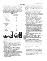
Appendix D. - Recommendations to User - 

Refrigerated

1.0  Hussmann Corporation provides instructions 

and recommendations for proper periodic 

cleaning. The user will be responsible for 

such cleaning, including the cleaning of low 

temperature equipment within the compartment 

and the cooling coil area(s). Cleaning practices, 

particularly with respect to proper refrigerator 

unloading and warm-up, must be in accordance 

with applicable recommendations.

Appendices (Cont'd)

Summary of Contents for DBP-03

Page 1: ...DBP DBRP 01 03 ISLAND PRODUCE p n IGIP DBP DBRP 01 03 0508 INSTALLATION OPERATION GUIDE CHINO DBP DBRP 01 03 ISLAND PRODUCE Rev 0508 Installation Operation Manual...

Page 2: ...s Information on DBP DBRP 01 03 Island Produce Cases Shipping Damage All equipment should be thoroughly examined for shipping damage before and during unloading This equipment has been carefully inspe...

Page 3: ...ain Ref 6 24 16 26 1 8 DBRP 03 Shown with Optional Ref High Center Divider and Refrigerated Lighted Shelves Scale 3 8 30 Optional Ref High Center Divider and Ref Lighted Shelves Optional Base Display...

Page 4: ...ty are maintained at or below 75 F and 55 relative humidity DO NOT allow air conditioning electric fans ovens open doors or windows etc to create air currents around the merchandiser as this will impa...

Page 5: ...and outside rear mullion on both cases to be joined 5 Apply liberal bead of case joint sealant butyl to dotted area shown in figure first case Apply heavy amount to cover entire shaded area DO NOT US...

Page 6: ...means to prevent freezing The water seal should be insulated to prevent condensation Hose Reel If an optional hose reel is ordered it will be installed at the factory The water supply valve is locate...

Page 7: ...rator outlet 2 From a refrigerant pressure temperature chart determine the saturation temperature at the observed suction pressure 3 Measure the temperature of the suction gas at the thermostatic remo...

Page 8: ...in and around the case area free of foreign gasses and fumes or food will rapidly deteriorate 3 Maintain the display merchandisers temperature controls as outlined in the refrigerator section of this...

Page 9: ...orescent Lamps Fluorescent lamps are furnished with a shatterproof protective coating The same type of lamp with protective coating must be used if replaced This lamp has been treated to resist breaka...

Page 10: ...that no outside doors or windows are open allowing moisture to enter store FOR PROMPT SERVICE When contacting the factory be sure to have the Case Model and Serial Number handy This information is on...

Page 11: ...01 CASES W0500000 CROWN CASE WIRING DIAGRAM 115 VAC 50 60 Hz L1 N BUNDLE COLOR BLACK WHITE T STAT SUCTION SOLENOID VALVE FIXTURE LITHONIA SM132 125 02 1072 FIXTURE LITHONIA SM125 125 02 1073 SWITCH T...

Page 12: ...00001 2 POINT CASE WIRING DIAGRAM 115 VAC 50 60 Hz L1 N BUNDLE COLOR BLACK WHITE T STAT SUCTION SOLENOID VALVE FIXTURE LITHONIA SM132 125 02 1072 FIXTURE LITHONIA SM125 125 02 1073 SWITCH TOGGLE 125 0...

Page 13: ...OINT CASE WIRING DIAGRAM 115 VAC 50 60 Hz L1 N BUNDLE COLOR BLACK WHITE T STAT SUCTION SOLENOID VALVE FIXTURE LITHONIA SM132 125 02 1072 FIXTURE LITHONIA SM125 125 02 1073 SWITCH TOGGLE 125 01 0329 BU...

Page 14: ...SES W0500003 8 CASE WIRING DIAGRAM 115 VAC 50 60 Hz L1 N BUNDLE COLOR BLACK WHITE T STAT SUCTION SOLENOID VALVE FIXTURE LITHONIA SM132 125 02 1072 FIXTURE LITHONIA SM125 125 02 1073 SWITCH TOGGLE 125...

Page 15: ...004 10 CASE WIRING DIAGRAM 115 VAC 50 60 Hz L1 N BUNDLE COLOR BLACK WHITE T STAT SUCTION SOLENOID VALVE FIXTURE LITHONIA SM132 125 02 1072 FIXTURE LITHONIA SM125 125 02 1073 SWITCH TOGGLE 125 01 0329...

Page 16: ...S W0500005 12 CASE WIRING DIAGRAM 115 VAC 50 60 Hz L1 N BUNDLE COLOR BLACK WHITE T STAT SUCTION SOLENOID VALVE FIXTURE LITHONIA SM132 125 02 1072 FIXTURE LITHONIA SM125 125 02 1073 SWITCH TOGGLE 125 0...

Page 17: ...6 14 CASE WIRING DIAGRAM 115 VAC 50 60 Hz L1 N BUNDLE COLOR BLACK WHITE T STAT SUCTION SOLENOID VALVE FIXTURE LITHONIA SM132 125 02 1072 FIXTURE LITHONIA SM125 125 02 1073 SWITCH TOGGLE 125 01 0329 BU...

Page 18: ...07 9 OCTAGON CASE WIRING DIAGRAM 115 VAC 50 60 Hz L1 N BUNDLE COLOR BLACK WHITE T STAT SUCTION SOLENOID VALVE FIXTURE LITHONIA SM132 125 02 1072 FIXTURE LITHONIA SM125 125 02 1073 SWITCH TOGGLE 125 01...

Page 19: ...SSMANN CORPORATION 13770 RAMONA AVENUE CHINO CA 91710 909 590 4910 LIC 644406 1 2 3 1 1 04 08 05 T WIRESCHEMATICS NEW WIRING DBRP 03 8 W0500008 DBRP 03 8 COIL PGS 2 3 6 115V 1 PHASE 50 60HZ 1 34 AMP 2...

Page 20: ...N CORPORATION 13770 RAMONA AVENUE CHINO CA 91710 909 590 4910 LIC 644406 1 2 3 1 1 04 08 05 T WIRESCHEMATICS NEW WIRING DBRP 03 32 W0500020 DBRP 03 32 COIL PGS 2 3 6 115V 1 PHASE 50 60HZ 1 34 AMP 225...

Page 21: ...HRH 561536 COIL PGS 2 3 6 115V 1 PHASE 50 60HZ 1 34 AMP 225 02 0040 M M TERMINAL BLOCK 125 01 0295 L1 L2 L3 N G DEFROST TIMER PARAGON 8045 20 208 V 60 Hz 125 01 0715 M YELLOW C 2 1 3 R S POWER 208 230...

Page 22: ...HRH COIL PGS 2 3 6 115V 1 PHASE 50 60HZ 1 34 AMP 225 02 0040 M M TERMINAL BLOCK 125 01 0295 L1 L2 L3 N G DEFROST TIMER PARAGON 8045 20 208 V 60 Hz 125 01 0715 M YELLOW C 2 1 3 R S POWER 208 230 VAC 6...

Page 23: ...6B GE FAN 9W 4 125 01 0615A 60A CONDENSING UNIT COPELAND FJAM A150 CFV 020 225 03 7510 RLA 10 9A MCC 15 7A LRA 56 A M C R CONDENSING UNIT SAFETY SWITCH FLOAT SWITCH FISHER EVAPOWAY DM20WW 3D 2000W 240...

Page 24: ...installer should perform a complete start up evaluation prior to the loading of food into the refrigerator which includes such items as a Initial temperature performance Coils should be properly fed...

Page 25: ...product 2 Is the product loaded beyond the Safe Load Line markers 3 Are the return air ducts blocked 4 Are the entering air ducts blocked 5 Is a dumped display causing turbulent air flow and mixing wi...

Page 26: ...temperature recovery Food store refrigerators are not food chillers nor can they reclaim quality lost through previous mishandling d Care must be taken when cross merchandising products to ensure that...

Page 27: ...___________________________ _______________ ___________________________________________________________________________________________________ _______________ ________________________________________...

Reviews: