
Rev. 0508
7
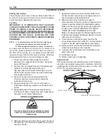
Access to TX valves and Drain Lines
Mechanical -
Remove product from end of case. Remove
product racks. Remove refrigeration and drain access
panels (labeled). TX valve (mechanical only) and drain are
located under each access panel at end of the case.
Electronic -
The Electronic Expansion valve master and
slave cylinder(s) are located within the electrical access
panel(s).
Electronic Expansion valve (Optional)
A wide variety of electronic expansion valves and case
controllers can be utilized. Please refer to EEV and
controller manufacturers information sheet. Sensors for
electronic expansion valves will be installed on the coil inlet,
coil outlet, and in the discharge air. (Some supermarkets
require a 4th sensor in the return air). Case controllers will
be located in the electrical raceway or under the case.
Thermostatic Expansion valve Location
This device is located on the same side as the refrigeration
stub. A balanced port expansion valve model is furnished
as standard equipment, unless otherwise specified by
customer.
Expansion valve Adjustment
Expansion valves must be adjusted to fully feed the
evaporator. Before attempting any adjustments, make
sure the evaporator is either clear or very lightly covered
with frost, and that the fixture is within 10°F of its expected
operating temperature.
Measuring the Operating Superheat
1. Determine the suction pressure with an accurate
pressure gauge at the evaporator outlet.
. From a refrigerant pressure temperature chart,
determine the saturation temperature at the
observed suction pressure.
3. Measure the temperature of the suction gas at the
thermostatic remote bulb location.
4. Subtract the saturation temperature obtained in step
No. from the temperature measured in step No. 3.
5. The difference is superheat.
6. Set the superheat for 5°F - 7°F.
T-STAT Location
T-STATS are located under access panels on the end of
the case.
Refrigeration (Cont'd)
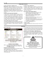
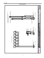
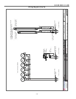
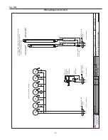
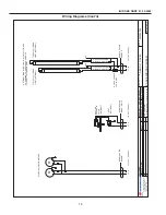
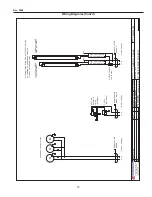
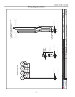
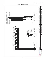
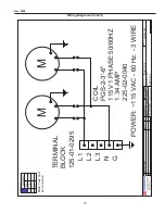
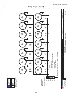
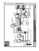
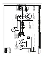
Electrical
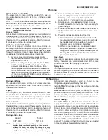
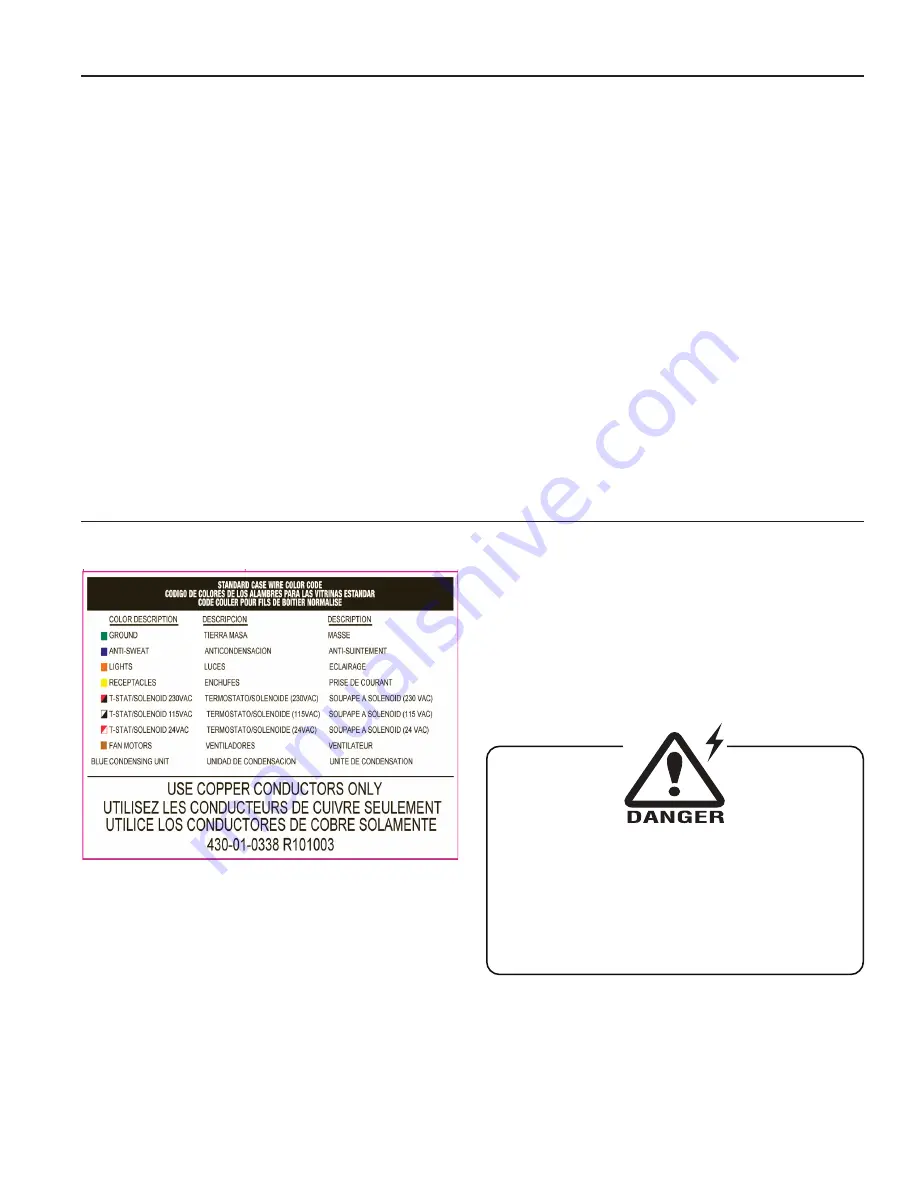
Wiring Color Code
CASE MUST BE GROUNDED
NOTE: Refer to label illustrated above that is affixed to case
to determine the actual configuration as checked in the
“TYPE INSTALLED” boxes.
Electrical Circuit Identification
Standard lighting for all models will be full length fluorescent
lamps located within the case at the top.
The switch controlling the lights, the plug provided for
digital scale, and the thermometer are located at the rear
of the case mullion.
The receptacle that is provided on the exterior back of these
models is intended for computerized scales with a five amp
maximum load, not for large motors or other high wattage
appliances. It should be wired to a dedicated circuit.
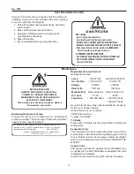
Electrical Service Receptacles (When Applicable)
The receptacles located on the exterior of the merchandiser
are intended for scales and lighted displays. They are not
intended nor suitable for large motors or other external
appliances.
BEFORE SERVICING
ALWAYS DISCONNECT ELECTRICAL
POWER AT THE MAIN DISCONNECT
WHEN SERVICING OR REPLACING ANY
ELECTRICAL COMPONENT.
This includes (but not limited to) Fans, Heaters
Thermostats, and Lights.