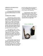
Replacing or cleaning of the ther-
mometer is accomplished by removing the
three screws securing the thermometer to
its bracket. Remove the screws holding
the lower edge of the return air grill. Re-
move the product and product trays. Lift
up and remove the panel that grill was se-
cured to. The RTV caulking in the corner
may have to be removed first.
Loosen the screw to the clamp
holding thermometer s ensing element.
Remove the element. Assemble in reverse
order making sure to thread the sensing
lead of the new thermometer through
mounting bracket first.
ELECTRICAL BOX –
The electrical box contains the de-
frost time clock, temperature control,
power switch, and terminal board. The
box is capable of sliding out of the con-
densing unit compartment for servicing
convenience.
Access is gained by removing the
bottom louvered panel and the electrical
box cover. The cabinet supply breakers
should be disconnected before removing
the cover.
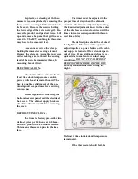
DEFROST TIME CLOCK –
The timer is factory pre-set for two
defros t cycles per 24 hours at 6:00 a.m.
and 6:00 p.m. with a 40 minute failsafe.
This means there are 4 pins in the time
face.
The timer must be adjus ted to the
proper time of day when the cabinet is
started. The timer is adjusted by turning
the knurled adjustment know in the center
of the dial face counter-clockwise until the
timer indicator corresponds with the cor-
rect time of day.
The defrost pins should be checked
for tightness. The timer will require re-
adjusting after a power failure or the cabi-
net supply is turned off for extended peri-
ods of time. If an additional defros t is re-
quired due to ambient or cabinet usage
conditions,
DO NOT PUT A DEFROST
DURING THE MIDDLE OF THE DAY.
Put any additional defrost during the
night.
Defrost is time initiated and temperature
terminated.
If the thermostat should fail, the

