99-18258-I002_A
5/18/2010
12
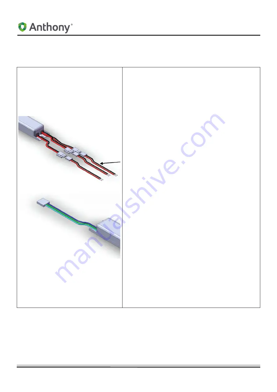
MOUNTING THE LED POWER SUPPLIES
Multi-Fixture Driver
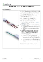
1. Install the LED power supply in the same location where the
ballast was fitted or in the general location for ease of wire
connection.
2. Mount the LED power supply using two #8 tapping screws
saved when the ballast was removed.
NOTE: Installer may have to drill two holes in raceway
to accommodate LED power supply.
NOTE: The LED power supply case is grounded.
Attach the LED power supply to a ground point in the
refrigerated case either directly with a screw or by
using the green wire to attach to a remote point.
3.
Connect LED Light fixture wire connectors to LED power
supply using plug assembly provided.
Refer to „RETROFIT
PARTS LIST” on page 3.
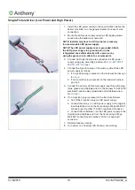
4. Connect the 3-position plug on the primary side of the LED
power supply as follows:
a. If a 3-position plug is present on the load wire harness go
to
step 5.
b. If no 3-position plug is present on the load wire harness
go
step 6.
5. Connect the primary LED power supply input 3-position
plug (blue, green and white/blue wires) to the harness
120-240 VAC electrical 3-position plug (blue/white and
white/blue wires). Go to
step 7.
6. If no 3-position plug is present on the load wire harness:
a. Cut off the 3-position plug on LED power supply.
b. Connect the blue (+) on LED power supply to the original
load blue/white wire on the frame using a Wago Wall-NUT
connector part number 773-162 or approved connector.
a. Connect the white/blue (-) on the LED power supply to the
original load white/blue wire from the frame using a Wago
Wall-NUT connector part number 773-162 or approved
connector.
7. Reinstall raceway cover(s).
8. Turn power on and verify LED fixture(s) are working.
Summary of Contents for HGM-1 BS
Page 2: ......
Page 4: ......
Page 70: ...Hussmann Corporation 12999 St Charles Rock Road Bridgeton MO 63044 2483 www hussmann com...


