LN
Technical Data Sheet
2 of 6
HUSSMANN CORPORATION, Bridgeton, MO 63044-2483 U.S.A.
LN
A
B
C
5
(127)
2
7/8
(98)
5
9/16
(141)
Refrig. Outlet
Water Seal
Electrical
Waste Outlet
(See Note*)
19
1/8
( 4 8 6 )
39
(991)
33
3/8
(848)
35
7/8
(911)
45
3/4
(1161)
32
3/8
(824)
41
5/8
(1057)
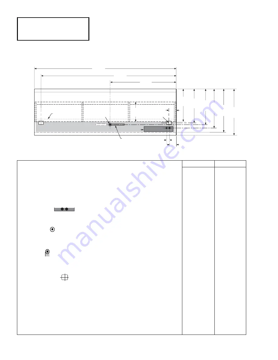
Access Area
(Gray)
Base Rail
Engineering
Plan Views
Dimensions shown as inches & (mm).
8 ft
12 ft
General
(A)
Case Length
(without ends or partitions)
96
1
/
4
(2445)
144
1
/
2
(3670)
(Each end and insulated partition adds 2 in. (51 mm) to case line up.)
Maximum O/S dimension of case back to front
(includes bumper)
45
3
/
4
(1162)
45
3
/
4
(1162)
Back of case to front of splashguard
41
5
/
8
(1057)
41
5
/
8
(1057)
Back of case to O/S edge of front base rail
32
3
/
8
(822)
32
3
/
8
(822)
Width of base rail
2
1
/
8
(54)
2
1
/
8
(54)
Stub-up area (gray) between base rail and splashguard
7
5
/
8
(194)
7
5
/
8
(194)
Electrical Service
(Electrical Field Wiring connection point)
RH End of case to center of nearest knockout
5 (127)
5 (127)
Back O/S of case to center of knockout
39 (991)
39 (991)
Waste Outlets
(B)
RH End of case to the center of waste outlet
58
1
/
4
(1480)
72
1
/
4
(1835)
LH End of case to center of waste outlet
38 (965)
72
1
/
4
(1835)
Back O/S of case to center of waste outlet
35
7
/
8
(911)
35
7
/
8
(911)
Water Seal
Edge of water seal to center of waste outlet
11 (279)
11 (279)
O/S diameter of drip pipe lines
1
1
/
2
(38)
1
1
/
2
(38)
Note*: Field installed water seal outlet, tees and connectors are shipped with case.
Refrigeration Outlet
RH end of case to center of RH refrigeration outlet
5
9
/
16
(141)
5
9
/
16
(141)
(C)
LH end of case to center of LH refrigeration outlet
88
3
/
8
(2245)
138
7
/
8
(3527)
Back O/S of case to center of refrigeration outlet
33
3
/
8
(848)
33
3
/
8
(848)
Low Temperature
Narrow Island Models


