background image

Hussmann Corporation • Bridgeton, Missouri  63044-2483 U.S.A.

Innovator Door Installation and Service Instruction

P/N 0425683_M

9

6.  Rock the door out and pull the bottom hinge pin 
out from the bottom socket.

7.  Install the new door in reverse order.

8.  Adjust the torque on the new door. If needed, 
adjust sag.

INNOVATOR DOOR HINGE 
REPLACEMENT

The following provides supplemental information for 
the replacement of a worn hinge pin. In addition to the 
hinge pin, it is recommend that the following parts be 
replaced.

*Note: If a hinge pin is bent or worn because of 

improper shimming, the addition of a nylon spacer 
(item 7), attached to the door’s torque rod, may be 
required.

In order to address a worn hinge pin, it is necessary to 
remove the door from the frame. 

Note:  The new hinge pin supplied with this replace-
ment kit is longer than the existing hinge pin. These 
were designed to be backward compatible.

Tips for replacing the hinge pin and related components:

• Always replace components 1 through 6.

• Torque all retaining screws to 100 in-lbs.

• After removing the pin and spring, clean out any 

debris (nylon or metal shavings) that may

be remaining in the door’s “hinge pin /spring” socket.

• Make sure the hinge pin bushing (4551267) is 

installed onto the hinge pin (0453783)

• If the hinge pin is bent, it’s because the pin is rotat-

ing on its shaft instead of the top bell. This is most 
likely caused by improper shimming. To correct the 
issue, order the torque rod spacer (item 7) along with parts 
1 through 6.

REPLACING MAGNETIC GASKET 

Carefully remove the old gasket from the groove in the 
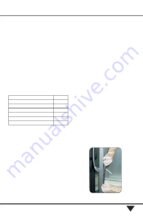
back of the door, Figure 9.

The new gasket will be easier to work with if it is at 
ambient temperature. Begin by lubricating the new  
gasket with a mild soap and water solution. 

Gasket

1. Top Hinge Plate

0543783

2. Top Hinge Plate Bushing

4551267

3. Top Hinge Spring (long)

1900391

4. Top Hinge Plate Socket (black)

4550103

5. Top Hinge Plate Socket (silver)

4550103

6. Torque Rod Spacer (*see note)

4551465

7. Socket Retainer Screw

0539743

Summary of Contents for Innovator

Page 1: ... Glass Door Innovator Innovator II Innovator III Spanish 0490775 French 0527088 Æ Installation Operation Manual P N 0425683_M February 2019 MANUAL I O INNOVATOR DOOR IMPORTANT Keep in store for future reference ...

Page 2: ...l We provide the Proposition 65 warning to stay in compliance with California State law It is your responsibility to provide accurate Proposition 65 warning labels to your customers when necessary For more information on Proposition 65 please visit the California State government website August 31 2018 BEFORE YOU BEGIN Read these instructions completely and carefully PERSONAL PROTECTION EQUIPMENT ...

Page 3: ...poration Contents General 1 Always Clear No Fog Glass 1 Shipping Damage 1 New Installations 1 Adjusting Closing Torque 1 Adjusting Door Sag 2 Conditioning Gasket 2 Innovator Door Maintenance 3 Replacing Doors 7 Innovator Door Hinge Replacement 9 Replacing Magnetic Gasket 9 Restoring Gasket Seal 10 Door Handle Replacement 12 Frame Heater Replacement 12 DASH Controller 14 EcoShine II EcoShine II Plu...

Page 4: ...ision G 1 Added Always Bright LED lighting information pages 12 through 18 pages 25 29 30 2 Added Optional Glass Door Anti Condensate Heater Controller information pages 11 12 3 Added Always Bright LED wiring diagrams pages 15 18 4 Added ballast change out direction page 21 ANSI Z535 5 DEFINITIONS DANGER Indicate s a hazardous situation which if not avoided will result in death or serious injury W...

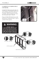
Page 5: ... SHIPPING DAMAGE All equipment should be thoroughly examined for shipping damage before and during unloading This equipment has been carefully inspected at our factory Any claim for loss or damage must be made to the carrier The carrier will provide any necessary inspection reports and or claim forms NEW INSTALLATIONS Untape the doors and remove shipping braces located at top and bottom of the doo...

Page 6: ...ashlight to identify any gaps between frame and gasket 3 Energize all anti sweat fan and light circuits for at least two hours but not more than four hours prior to initiating the refrigeration cycle 4 Monitor all gaps If gaps remain at the end of four hours follow the procedure for Restoring Gasket Seal beginning on page 6 of this manual 5 Initiate cooling sequence once gaps disappear Do not exce...

Page 7: ...e 1 A rusted torque cam socket assembly can cause excessive wear on the torque rod s spacer and sleeve bearing The result is a door that can seat far ther down the rod assembly to the point that it causes binding at the hold open bracket It can also cause the top hinge pin s sleeve bearing to deform If the door is seated too far down the torque rod assembly it most likely damaged the top hinge pin...

Page 8: ...U S Canada 1 800 922 1919 Mexico 1 800 890 2900 WWW HUSSMANN COM P N 0425683_M 4 Key Inspection Points Top Hinge Pin Hold Open Bracket Torque Rod Assembly Top Hinge Plate Hold Open Bracket ...

Page 9: ...onged high humid ity or cycling the frame s anti sweat heaters The best solution is to replace the torque rod assembly and hinge pinsleevebearing however iftheexternalfactors are not addressed this will be become a recurring problem Belowisanexampleofadamagedsleevebearing The compromised torque rod components caused the door to seat below its designed parameter Because the door has essentially bee...

Page 10: ... rod that does NOT require maintenance All components are intact and performing properly Below is a rod that has operated for prolonged periods of time in Type 1 conditions This rod assembly should be replaced Sleeve bearing and spacer are in excellent condition Sleeve bearing and spacer have been compromised ...

Page 11: ...m hinge pin up and out of the bottom hinge socket Hold the hinge pin with a 1 2 in 13 mm open end wrench to keep it from spinning out and stripping the socket See Figure 3 Lift up Screwdriver Figure 3 Loosening Torque on the Door LOCK OUT TAG OUT To avoid serious injury or death from electrical shock always disconnect the electrical power at the main disconnect when servicing or replacing any elec...

Page 12: ...grees to access the screws 4 Use a flat blade screwdriver as shown in Figure 6 to lift the door retainer over the shoulder screw 5 Push down the top hinge pin until it clears the top socket using a flat blade screwdriver as shown in Figure 7 With finger hold the hinge pin in the door to keep it from popping out Tape may be used to temporarily hold the hinge pin once door is removed Figure 4 Removi...

Page 13: ...ble Tips for replacing the hinge pin and related components Always replace components 1 through 6 Torque all retaining screws to 100 in lbs After removing the pin and spring clean out any debris nylon or metal shavings that may be remaining in the door s hinge pin spring socket Make sure the hinge pin bushing 4551267 is installed onto the hinge pin 0453783 If the hinge pin is bent it s because the...

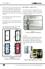
Page 14: ...to dry the gasket before closing door on clean door frame RESTORING GASKET SEAL Occasionally a crimped or damaged gasket can cause gaps in the seal Figure 11 leading to frost formation on the doors Use this procedure to close gaps and end frost formation on doors Locate Gaps Normally interior case lighting will provide enough light to see gaps In some cases the only way to see gaps is to provide a...

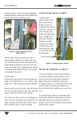
Page 15: ...on that the gasket is near the melting point If possible direct the hot air onto the gas ket and also through the gap between the gasket and mullion This will help to heat both sides of the gasket Refer to Figure 13 A and B As the gasket softens and becomes pliable the magnet in the gasket should pull it across the gap As the gap closes move heat down to create a zippering effect as shown in Figur...

Page 16: ...e gasket completely with a fresh cloth or paper towels before closing the door on a clean door frame DOOR HANDLE REPLACEMENT Carefully pull the magnetic gasket out of the groove nearest the handle to expose the mounting screws as shown in Figure 16 Remove the screws and replace the handle After reinstalling screws carefully push gasket back into groove If needed use a mild soap and water solution ...

Page 17: ... heater wire is connected check resistance ohm reading before replacing wireway covers This will ensure that heater wire was not broken during installation Wiring diagrams are shown in Figure 19 After covers are reinstalled turn power on and verify that heaters are working properly LOCK OUT TAG OUT To avoid serious injury or death from electri cal shock always disconnect the electrical power at th...

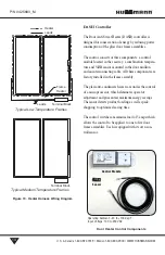
Page 18: ...ss anti condensate heaters are under the control of a microprocessor which eliminates operator adjustment and guarantees maximum energy savings The sensor detects product loading as well as peak shopping to optimize clearing time The control switches a maximum load of 5 amps which allows the control to be applied to one to five door frame assemblies Each is equipped with its own con trol sensor He...

Page 19: ...iring around the gasket 5 Important Verify the sensor board perimeter is com pletely sealed Use electrical tape to hold wiring in position at the center of the mullion This will avoid damage when replacing the cover Sensor Control Box 6 The control box is mounted to the ballast tray with 8 x 3 8 sheet metal screws 7 Connect the sensor harness to the control box Door Heater Harness 8 Connect the in...

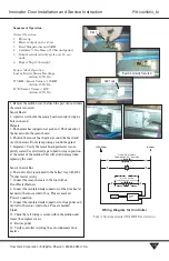
Page 20: ...0 hours That is 5 7 years of continuous 24 hour operation Light Switch LOCK OUT TAG OUT To avoid serious injury or death from electri cal shock always disconnect the electrical power at the main disconnect when servicing or replacing any electrical component This includes but is not limited to such items as doors lights fans heaters and thermostats 27mm 42mm 27mm 55mm 27mm 42mm 27mm 55mm 27mm 42mm...

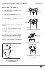
Page 21: ...ighting is polarity sensitive LED light fixtures are polarity sensitive The power supply positive wire must be electrically connected to the red wires of the LED fixture The power supply negative wire must be connected electrically to the black wires See Wiring Diagrams beginning on Page 17 Figure 20 Disconnect Wiring End Fixture Shown Mullion Wiring Top of LED Wiring Harness Mullion Wiring Slide ...

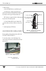
Page 22: ...ED fixture is shipped with a protective film over the lens Be sure to remove this film 7 Install replacement LED fixture LED POWER SUPPLY REPLACEMENT Power supplies are located in the wireway below the door frame as shown in Figure 22 To access the wireway remove the bumper then remove the 8 hex head screws that hold on the front painted panel Mullion Wiring Mullion LED Fixture 2 Mounting Clip Cle...

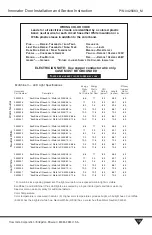
Page 23: ...0K 68 in 9 4 10 9 85 66 1 65 0530541 EcoShine II Reach In Walk In CS 3500K 72 in 10 0 11 6 85 70 4 65 0530524 EcoShine II Reach In Walk In 4000K 48 in 6 6 7 7 85 48 5 65 0530527 EcoShine II Reach In Walk In 4000K 56 in 7 7 9 0 85 55 1 65 0530530 EcoShine II Reach In Walk In 4000K 62 in 8 2 9 5 85 59 5 65 0530533 EcoShine II Reach In Walk In 4000K 68 in 9 4 10 9 85 66 1 65 0530539 EcoShine II Reach...

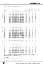
Page 24: ...hine II Plus Reach In Walk In 4000K 68 in Center 16 5 20 0 80 67 5 60 0523428 EcoShine II Plus Reach In Walk In 4000K 68 in RH End 10 1 20 0 80 67 5 60 0523429 EcoShine II Plus Reach In Walk In 4000K 68 in LH End 10 1 20 0 80 67 5 60 0523430 EcoShine II Plus Reach In Walk In 4000K 72 in Center 24 4 29 5 80 71 60 0523431 EcoShine II Plus Reach In Walk In 4000K 72 in RH End 14 7 29 5 80 71 60 052458...

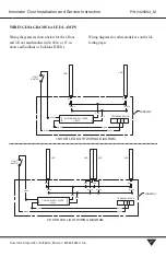
Page 25: ...coShine or EcoShine II LEDs Wiring diagrams for other models are on the fol lowing pages LIGHT SWITCH WIREWAY LED LED TERMINAL BLOCK 1 DOOR LED LIGHT WIRING DIAGRAM POWER SUPPLY 24VDC 100W OUTPUT INPUT WHITE WHITE BLUE RED RED RED BLACK BLACK BLACK BLACK BLACK LIGHT SWITCH WIREWAY LED LED TERMINAL BLOCK POWER SUPPLY 24VDC 100W 2 DOOR LED LIGHT WIRING DIAGRAM RED RED RED RED RED BLACK WHITE WHITE O...

Page 26: ...VDC 100W 3 DOOR LED LIGHT WIRING DIAGRAM OUTPUT INPUT LED LED LED LED BLUE RED RED RED RED RED RED RED BLACK BLACK BLACK BLACK WHITE WHITE BLACK BLACK BLACK BLACK BLACK BLACK BLACK BLACK Wiring diagrams are shown below for RLNIE merchandisers with 60 in EcoShine II LEDs LIGHT SWITCH WIREWAY BLACK BLACK BLACK BLACK OUTPUT INPUT BLACK WHITE LED LED LED LED LED LED TERMINAL BLOCK 3 DOOR LH SIDE COMPA...

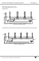
Page 27: ...D RED RED RED RED RED BLACK BLACK BLACK BLACK WHITE WHITE BLACK BLACK BLACK BLACK BLACK BLACK BLACK BLACK Wiring diagrams are shown below for 3 door and 4 door merchandisers with 60 in and 67 in EcoShine II LEDs LIGHT SWITCH WIREWAY BLACK OUTPUT INPUT BLACK BLACK BLACK BLACK BLACK BLACK BLACK BLACK BLACK BLACK RED RED RED RED RED RED RED RED RED BLUE WHITE LED LED LED LED LED LED LED LED TERMINAL ...

Page 28: ...BLACK BLUE RED RED RED RED RED RED RED RED RED RED RED RED RED RED RED RED RED RED RED RED RED BLACK BLACK BLACK BLACK Replacement Parts List Doors Description Mfg Part No Door Innovator Med Temp Black Lh 0425617 Door Innovator Med Temp Black Rh 0425618 Door Innovator Med Temp Gray Lh 0425619 Door Innovator Med Temp Gray Rh 0425620 Door Innovator Med Temp 311 Oyster Lh N A Door Innovator Med Temp ...

Page 29: ...or II Gray Rh 0440472 Door Innovator II 311 Pearl Lh 0441635 Door Innovator II 311 Pearl Rh 0441636 Door Innovator II Black Lh Standard 0458383 Door Innovator II Black Rh Standard 0458384 Door Innovator II Gray Lh Standard 0458457 Door Innovator II Gray Rh Standard 0458458 Note Innovator II Doors are not available for RLT Door Innovator III Med Temp Black Lh 0519946 Door Innovator III Med Temp Bla...

Page 30: ...36 Door Innovator III Always Clear Black Rh Standard 0519937 Door Innovator III Always Clear Gray Lh Standard 0519938 Door Innovator III Always Clear Gray Rh Standard 0519939 Door Innovator III Always Clear Black Lh RLT 0519942 Door Innovator III Always Clear Black Rh RLT 0519943 Door Innovator III Always Clear Gray Lh RLT N A Door Innovator III Always Clear Gray Rh RLT N A Door Innovator III Med ...

Page 31: ...ireway 2 Door Top Lh Gray Bottom Rh 0428575 Cover Wireway 2 Door Top Lh 311 Pearl Bottom Rh 0442048 Cover Wireway 2 Door Top Rh Black Bottom Lh 0428567 Cover Wireway 2 Door Top Rh Gray Bottom Lh 0428576 Cover Wireway 2 Door Top Rh 311 Pearl Bottom Lh 0442049 Cover Wireway 3 Door Top Lh Black Bottom Rh 0428568 Cover Wireway 3 Door Top Lh Gray Bottom Rh 0428577 Cover Wireway 3 Door Top Lh 311 Pearl ...

Page 32: ...ard 0428574 Cover Wireway End 311 Pearl Standard 0442047 Cover Wireway End Black RLT 0304949 Cover Wireway End Gray RLT 0305004 Cover Wireway End 311 Pearl RLT N A Cover Wireway Mullion Black Standard 0428564 Cover Wireway Mullion Gray Standard 0428573 Cover Wireway Mullion 311 Pearl Standard 0442046 Cover Wireway Mullion Black RLT 0304948 Cover Wireway Mullion Gray RLT 0305003 Cover Wireway Mulli...

Page 33: ...432599 Harness Female Receptacle Black 0432600 Harness Female Receptacle Gray 0432601 Harness Female Receptacle 311 Pearl N A Harness Opposite Swing Black 0432612 Harness Opposite Swing Gray 0432613 Harness Opposite Swing 311 Pearl N A Heater Frame Wire 2 Door Innovator Low Temp Standard 0428601 Heater Frame Wire 3 Door Innovator Low Temp Standard 0428602 Heater Frame Wire 4 Door Innovator Low Tem...

Page 34: ...425610 Molding Joint 311 Pearl Standard 0442337 Molding Joint Black RLT 0456200 Molding Joint Gray RLT 0456201 Molding Joint 311 Pearl RLT N A Top Hinge Plate 0543783 Top Hinge Plate Bushing 4551267 Top Hinge Spring long 1900391 Top Hinge Spring short 0543782 Top Hinge Plate Socket black 4550103 Top Hinge Plate Socket silver 4550103 Torque Rod Spacer 4551465 Socket Retainer Screw 0539743 Plug 1 4 ...

Page 35: ...p Holder Top Lamp Holder Bottom Socket Bottom Hinge Socket Top Hinge Screw Case End Shoulder Closer Door Cover Wireway Heater Frame Wire Pin Top Hinge Innovator and Innovator II Door and Frame Part Identification Chart NOTE Top Lamp Holder has Two Leads Bottom Lamp Holder has Three Leads Clip SPN 5 Strain Relief Screw Handle Handle Standard Molding End Molding Joint Screw BInder Post Electronic La...

Page 36: ... information or other support contact your Hussmann representative Please include the model and serial number of the product Hussmann Corporation Corporate Headquarters Bridgeton Missouri U S A 63044 2483 01 October 2012 ...

Reviews: