background image

©2007 HUSSMANN CORPORATION • BRIDGETON, MO  63044-2483 U.S.A.
U.S. & CANADA 1-800-504-4828 • WWW.CHILLCHAMBER.HUSSMANN.COM

3

P/N 31033596_B

01 June 2007

MAXI-140

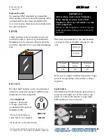
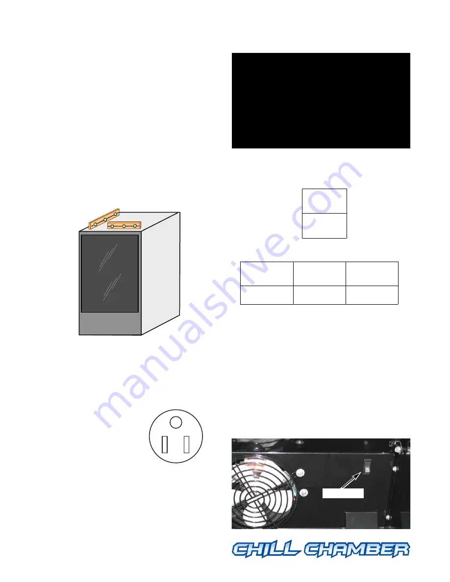
Optional Leg Kit

To maintain NSF standards of cleanability
when sealing cannot be done, Hussmann offers
optional leg kits that raises the MAXI-140 
four or six inches. Directions are included with
the optional leg kit. 

LEVEL

Chill Chambers must be level front-to-back
and side-to-side to operate at peak efficiency.
Shimming may be necessary. Ensure all sides
are firmly supported. Use care when shimming
legs.

PLUG IN

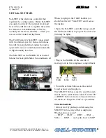
Put the Chill Chamber on its own dedicated
electrical circuit with ground. 12AWG is the
minimum size wire acceptable.

• The 

MAXI-140

requires a dedicated
15 Amp circuit with
grounded wall receptacle 
(NEMA 5-15P)

• Do not use extension
cords. Never use adapters.

• If in doubt, call an electrician.

Electrical requirements for the merchandiser
are stated on the serial plate attached to the
unit.

If the power supply oscillates beyond the range
given in the preceding table, install a voltage
regulator.

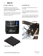
Light Switch

The MAXI-140 Chill Chamber light switch is
located on the right rear of the interior top
panel. It controls the exterior canopy light;
LED lighting is 

ON

at all times.

MAXI-140

MAXI-140

MAXI-140

MAXI-140

NEMA 5-15P

MAXI-140

MAXI-140

1000 VA

Nominal

Voltage

Minimum

Voltage

Maximum

Voltage

120

108

132

Light switch

IMPORTANT:

After leveling, wait at least 30 minutes
before turning on power to the Chill
Chamber to allow any oil residue to return
to the compressor. 

Oil not in the compressor at start up may
cause permanent damage not covered by
warranty.

Summary of Contents for MAXI-140

Page 1: ...MAXI 140 Operator s Manual P N 31033596_B 01 June 2007...

Page 2: ...entifying the type of application for which the case was certified ANSI NSF 7 Type II Display Refrigerator Freezer Beverage Cooler Intended for 80 F 55 RH Ambient Application This equipment is intende...

Page 3: ...01 June 2007 MAXI 140 MAXI 140 MAXI 140 MAXI 140 MAXI 140 To reduce the risk of fire electrical shock or injury when using your Chill Chamber Always use a dedicated circuit with the Amperage stated on...

Page 4: ...ppropriate equipment to safely lift and move the Chill Chamber to the preferred location in your business Carefully remove the shipping box Avoid scratching the Chill Chamber Recycle packing materials...

Page 5: ...dicated 15 Amp circuit with grounded wall receptacle NEMA 5 15P Do not use extension cords Never use adapters If in doubt call an electrician Electrical requirements for the merchandiser are stated on...

Page 6: ...ng The top door hinge has slots that allow the door to be adjusted if the gasket doesn t seal completely Use a nut driver to loosen the four hex head screws just enough to allow the hinge to move back...

Page 7: ...NET scroll across the display Open the Safe NET controller using a small flat blade screwdriver to pop off the oval cover this may be tight Plug in the MAXI 140 Be careful of moving parts in the compr...

Page 8: ...inutes are displayed then press SELECT Hours should flash With hours flashing use the UP or DOWN button until the correct hour is displayed Safe NET uses a 24 hour or military clock where 12 is noon P...

Page 9: ...st the temperature display may move up 2 3 F 1 2 C Avoid opening the door during the defrost cycle Defrost is necessary because the Chill Chamber operates at temperatures below freezing 22 F 5 5 C Def...

Page 10: ...ndEF number of defrosts determines the number of defrosts that occur in a 24 hour period beginning with the StAr first defrost parameter The maximum number of defrosts allowed in a 24 hour period is...

Page 11: ...the display and gently press into place Run Before Stocking Allow the Chill Chamber to run at least 30 minutes before stocking LOADING 1 Add the maximum quantity 66 bottles allowed of Anheuser Busch...

Page 12: ...based cleaners on acrylic parts Solvent oil or acidic based cleaners on any interior surfaces A hose on display or interior lights or any other electrical connection Do First disconnect electrical po...

Page 13: ...he upper shelf Make sure that each shelf mounting slot engages with its mounting screw 7 Install the near most LH side and RH side screws into the upper shelf 8 Place the lower shelf flush against the...

Page 14: ...ug unit before replacing lamp Restocked beer may freeze 1 Sell all product in the unit 2 Turn off lamp switch Unplug the unit 3 Remove shelves 4 Remove the two recessed screws from the canopy Screws a...

Page 15: ...cing LED light strip Restocked beer may freeze 1 Follow steps 1 through 7 of Fluorescent Lamp Replacement 2 Disconnect the LED connector 3 With a screwdriver loosen but do not remove the LED lighting...

Page 16: ...il from blocking with ice Very frequent door openings will eventually have an impact on product temperature and cause it to rise Avoid holding the door open while deciding on product selection countin...

Page 17: ...ator Unusual Noise Unit not level Reposition and level the unit Unit contacting structure Reposition unit to provide space on all sides Rear grille loose Fasten grille to attenuate sound Slow to cool...

Page 18: ...ssemblies If within the warranty period it can be proven to the satisfaction of Hussmann s warranty administration organization that there is impaired visibility through a multi glass assembly caused...

Page 19: ...MERCHANTABILITY OR FITNESS AND HUSSMANN NEITHERASSUMES NORAUTHORIZESANY PERSON TOASSUME FOR IT ANY OTHER OBLIGATION OR LIABILITY IN CONNECTIONWITHTHE SALE OF ITS PRODUCTS ORANY PARTTHEREOF THISWARRAN...

Page 20: ...22 F...

Reviews: