IGIC-RMID-0109
10
(I)
(J)
(K)
2. Allow to dry one hour.
3. Trim off the top of the
peg.
4. Allow to dry completely
(24 hours)
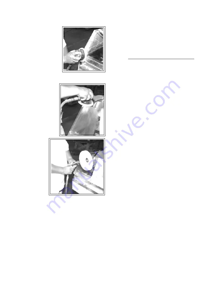
SANDING AND BUFFING
1. After allowing ample time
for cement to dry, remove
all tape and sand down the
plexiglass corners
(I-J)
and tops of straight section
(L)
(where peg is located)
with 200 mic sandpaper
until flush. Switch to 30
mic sandpaper covering
all 220 mic marring.
2. Place buffing wheel in
drill motor and apply
white buffing rouge un-
til wheel has been fully
covered.
3. Buff out all marring at
seams.
(K)
IMPORTANT:
keep
wheel
moving - do not stop
in one spot while
wheel
is moving. Stop-
ping will cause
plexiglass burning.
PLEXIGLASS COR-
NER SUPPORT:
1. Clean all white
residue off inside
corners with
clean cloth.
2. Insert the buffed
out (clear) angle support and press against the corner
to make sure it fits flush on all edges.
3. Clamp angle support firmly into the corner of the case
(G).
4. Have one person hold the support firmly against the
corner while another glues the plex
(H),
but not so
firmly that glue cannot penetrate seam. Start at the
bottom of the outside seam and work your way to
the top. Release enough glue so that joint is penetrated.
Tur ning the bottle completely upside down should
supply enough pressure to allow the cement to flow
freely. Use only what is needed to bind the edges. Over-
flow can scar the plexiglass and needs to be cleaned
up immediately with a
CLEAN, LINT-FREE TOWEL OR
RAG
. You may need to apply a
small
amount of pres-
sure to the cement to help it flow out of the tube.
5. Allow glue to set for
at least 15 minutes.
REPLACE FLARE AND BUMPER
1. Replace flare, taking care not to bend it, (See first il-
lustration
(A-C)
in instructions), using 1/8" pop riv-
ets.
2. Screw in bumper channels.
3. Replace Corner Bumper.
4. Replace straight section bumper(s).
ACCESS PANELS
All ELECTRICAL and drain access panels are clearly la-
beled on the deck of the deli/cheese stand. The access
for condensing units (in the self contained units) is lo-
cated on the side of the stand, at the end. Ends of stand
are fitted for removal, if condensing unit has to be taken
out.
INSTALLING SPLASHGUARD
After merchandisers have been leveled and joined, and all
drip piping, ELECTRICAL and refrigeration work has been
completed, install the splashguards. Splashguards may be
sealed to the floor using a vinyl cove base trim. The size of
trim needed will depend on how much the floor is out of
level. NOTE: The splashguard must be removable to ac-
cess components behind it.
1. Remove all dirt and wax (etc.) from the area of the
splashguard to ensure a secure adhesion.
2. Apply a good contact cement to the trim, allowing for
proper dry-time.
3. Install trim to the splashguard so that it is flush with
floor.
DO NOT SEAL TRIM TO FLOOR!
Summary of Contents for RMID
Page 36: ...IGIC RMID 0109 36 ...


