5
B. The defrost initiation may be delayed for as long as 2 minutes after step
3 is completed.
The display will show “dF” once step 3 is completed, even with the protective
delay timing out. The “dF” will display for a while after defrost has terminated,
to allow the temperature to stabilize.
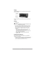
CAUTION:
Return the control knob to its original setting (Step 1) once
the manual defrost has been initiated.
Evaporator Fan Delay
On low temperature models, an evaporator fan delay is incorporated to delay
the fan operation until the evaporator is below its setpoint temperature,
following a defrost cycle.
On some low temperature models, the evaporator fan is briefly cycled to
dissipate the presence of vapor during the defrost cycle.
Service Procedures (for service personnel only)
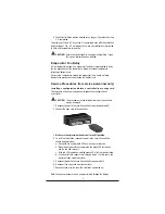
Installing a configuration file into a controller from a copy card
The copy card allows service personnel to update the configuration of
a controller.
CAUTION:
This procedure must be followed exactly or the controller
may be damaged.
1. Disconnect power to the case (the controller must be powered off).
*2. Connect the copy card to the controller.
3.
Make sure the adjustment knob is not in the Off position.
4. To start the installation, reconnect power to the case (the controller
should be powered on).
a. During the file transfer, both LEDs on the copy card turn on.
b. When the data transfer has completed, the green LED remains on
and the red LED turns off.
c. If the red LED remains on and the green LED is off, the transfer failed.
d. If the transfer fails, repeat step 1 through step 4. If it fails again, use
a different copy card or controller.
5. Disconnect power to the case (the controller is powered off).
6. Disconnect the copy card from the controller.
7. Reconnect power to the case (the controller is powered on).
Note: The above procedure can be easily performed through the display


