THREE BUTTON RULES
• Always start by pushing the
SELECT
button, watch what is
displayed. Which menu are you in?
— StUP — CLOC — DEFr — tEM — VALv — DiSP —
and cycles back to StUP
• Press the
SELECT
button until you are in the proper menu. Once in
the proper menu press the
UP
or
DOWN
button to enter the menu and
to scroll through the menu.
• Once at the menu item that you want, press the
SELECT
button until
the item flashes between the value and the title. You may have to press
the
SELECT
button more than once to get the item to flash.
• Then press the
UP
or
DOWN
button to change the item.
• Remember to push the
SELECT
button to save the item.
Also remember to set the passcode before any items can be changed.
• Pressing the
UP
or
DOWN
buttons at the same time acts as an escape
to go back out of the menus.
Safe-NET
™
DISPLAY & ALARM MODULES
DESCRIPTION
Safe-NET Display Module
The Safe-NET Display Module, shown below, is a temperature-
monitoring device. The display module reads and displays temperature
sensed by the product simulator temperature sensor mounted in the
refrigerated space. The display module notifies the user of alarms based
on preset alarm conditions.
OPERATION
Normal
During normal operating conditions, the product simulator tempera-
ture is displayed. The GREEN LED on the alarm module is lighted .
Product Temperature Alarms
The display module generates an alarm if the product simulator
temperature rises above the high alarm set point or drops below the
low alarm set point for the preset time duration.
When the display module generates a high temperature alarm, the
RED LED on the display module is lighted. Every 12 seconds,
PrHi
is
displayed for 3 seconds; for the remaining time, the product simulator
temperature is displayed.
When the display module generates a low temperature alarm, the
RED LED on the display module is lighted. Every 12 seconds,
PrLo
is
displayed for 3 seconds; for the remaining time, the product simulator
temperature is displayed.
For either alarm, the beeper on the alarm board beeps every 6 seconds.
Power Failure
If external power to the unit is interrupted, the backup battery on the
alarm board supplies power to maintain the non-volatile memory in
the display module.
To conserve power, the display LEDs are blanked except for a period of
6 seconds every 3 minutes when product temperature is displayed.
Product temperature alarms can be generated during external power
loss. The audible alarm is active only for product temperature alarms.
Low Battery
During normal operating conditions, the alarm module monitors
battery condition. The display shows
bAtt
when the battery becomes
low on power and the beeper on the alarm board beeps every 2 minutes
to indicate a low battery condition.
The low battery audible alarm is
active only when external power is applied.
Connection Failure
Loss of communication between the display module and the alarm
module activates an alarm. When the display module generates a loss of
communication alarm, the RED LED on the display module is lighted.
Every 12 seconds,
A-Er
is displayed for 3 seconds; for the remaining
time, the product simulator temperature is displayed. The beeper on
alarm board beeps every 30 seconds. The
A-Er
audible alarm is active
only when external power is applied.
Precedence of Alarms
Severity of the alarm determines the beeper action. The following table
shows the priority of the alarms.
An alarm with higher severity takes precedence over a low severity
alarm. For example, if there is a product alarm and low battery alarm:
•
The alarm board beeper beeps every 6 seconds to indicate the
product temperature alarm.
•
Indication of the low battery alarm is ignored by the beeper, but
is active in the display.
•
Every 12 seconds, the display shows
PrHi
for 3 seconds followed
by
bAtt
for 3 seconds. For the remaining time, product simulator
temperature is displayed.
Alarm Set Points
Refer to the manual that came with the specific case or model.
Notes:
•
A high temperature alarm typically activates during case startup.
This is normal since the refrigerated space requires an extended period
to reach operating temperature. Product must not be loaded until
operating temperature is reached. Premature stocking may result in
product loss.
•
Battery backup operation is possible for up to 6 hours. The initial
condition of the battery determines the length of time. Operation of
Safe-NET is compromised once the battery runs low. Product integrity
cannot be ensured until power is restored and the battery is replaced.
MODIFYING SETTINGS
The Safe-NET display module stores alarm set points and alarm delay
times for monitoring cases. The suggested default set points may be
modified.
Use a flat, narrow tool such as a small screwdriver to remove the cover
of the display module.
IMPORTANT!
•
Hussmann recommends against changing
any parameter
value other than those described herein. Modification of
any other parameter may result in unpredictable Safe-NET
operation.
• The user must monitor each case after altering product
alarm set points and/or product alarm time delays to verify
proper operation.
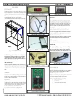
There are three visible buttons on the left hand side of the display
board
,
as indicated in Figure 2 on Page 1. Although labels are not
clear, buttons can be determined by their location.
The SELECT button is located near the top edge of the display board.
It is used to select the menus and to edit the menus.
The UP button is the left button of the two buttons located on the
bottom lineup of the display board. The DOWN is the right button of
the two buttons located on the bottom lineup of the display board.
The UP and DOWN buttons are used to move within and between
menus, and to increment or decrement values.
Safe-NET™ Self-contained Operating Instruction
Page
2 of 8 — P/N 0485005_B
© 2007 Hussmann Corporation • Bridgeton, Missouri 63044-2483 U.S.A.
www.hussmann.com/cstore/c_techinfo.htm
20 June 2007
Safe-NET Display Module with Top Cover
LED Indicators
Safe-NET Display Module with Cover Removed
Safe-NET Alarm Module
Green LED
SELECT Button
UP Button
DOWN Button
Alarm
Display
Action
Beeper
OFF Time
(seconds)
Severity
Product
HIGH/LOW
Alarm
PrHi/PrLo
6
1
Connection
Failure
A-Er
30
2
Low Battery
bAtt
120
3


