Notes:
•
The SELECT button is used to scroll through the following menus:
StUP
– Setup
CLoC
– Clock
dEFr
– Defrost
tEM
– Temperature
uALu
– Valve
diSP
– Display Default
•
User must enter valid password to edit parameter settings.
•
To edit any menu item, press either the UP or DOWN button to
enter the selected menu.
•
Use the SELECT button to modify and save the parameter once the
UP or DOWN button is pressed.
•
The display cycles between menu item and edited menu value once
the edited value is entered using the SELECT button, .
•
The display returns to showing the product simulator temperature
if no button is pressed for 12 seconds once the menu is displayed. User
must scroll through the menus using the SELECT button to return to
the SETUP menu.
•
Holding a button down has the same effect as pressing once.
PASSWORD
Entering the password is done in the SETUP menu. At the top of the
SETUP menu, press the UP button. The display will begin to cycle
between PASS and 0.
While 0 is being displayed, press the SELECT button to allow editing
of the value. With the Safe-NET display module flashing 0, use the UP
/DOWN buttons to increment or decrement the value until it reaches
595. 595 is the password value.
Once 595 is displayed, press the SELECT button. The display will
revert to cycling between PASS and 595. This enables editing of
parameters.
The user may now navigate the menu system and edit parameters as
necessary.
Note:
The password protected access remains active for 5 minutes. Each time a
new parameter is entered by pressing the ENTER key on the Hand-Held
device or the SELECT button on the Safe-NET display module, the
5 minute timer is restarted. After 5 minutes with no parameter entries,
the password value reverts to 0 and the password entry process must be
performed to regain access to critical parameters. The SETUP menu can
be navigated without a valid password in a “view only” mode.
MODIFYING SET POINTS
With the password active and the display reading product temperature,
use the SELECT button to scroll through the menus. Once the display
reaches the
StuP
menu, use the UP button until the display shows the
parameter to be modified:
•
To change the product low alarm set point, press the UP button
until the display cycles between
PrLo
and the current product low
alarm set point.
•
To change the product high alarm set point, press the UP button
until the display cycles between
PrHi
and the current product high
alarm set point.
•
To change the product alarm delay, press the UP button until
display cycles between
P-dL
and the current product alarm delay.
Once the desired menu item is displayed, press SELECT button. The
display cycles between the corresponding menu item and the VALUE.
Press the UP button to increment the value or the DOWN button to
decrement the value.
When the entered value begins flashing, press the SELECT button to
store the new value. The display cycles between the new value and the
menu item. Within 12 seconds after button activation, the display
starts showing the product temperature.
ALARMS
A red LED on the board turns on during alarm. The display will show
a four-character word for about 3 seconds alternating with a blank
display for 9 seconds. Following are details of alarms applicable to
self-contained cases.
Alarm with Sensor Number – “SEnS”
This alarm is generated when the control is initialized, and indicates
that the number of sensors entered in the control is different from the
number of sensors connected to the control. This Alarm can be cleared
only by changing the reading for number of sensors to 0 and resetting
the display module which then updates the reading to the number of
sensors connected. This is caused by the control not being set up
correctly or by a sensor having failed.
Alarm with Sensor reading – “noSn”
This alarm is generated when the display module is unable to read the
sensors for five consecutive seconds. This alarm clears automatically
when the control is able to read the sensors. This may be caused by a
sensor being disconnected or shorted. This alarm clears automatically
when the control is able to read the sensors.
Discharge Air High Alarm – “dSHi”
This alarm is generated when the average discharge air temperature in
the case, over the programmed alarm delay time, is higher than the
High Alarm value stored in the control. This alarm will clear if the
average discharge air temperature goes below the High alarm value.
T
HIS ALARM IS AVAILABLE ONLY IF DISCHARGE SENSORS ARE INSTALLED
.
Discharge Air Low Alarm – “dSLo”
This alarm is generated when the average discharge air temperature in
the case, over the programmed alarm delay time, is lower than the Low
Alarm value stored in the control. This alarm will reset if the average
discharge air temperature goes higher than Low alarm value.
T
HIS ALARM IS AVAILABLE ONLY IF DISCHARGE SENSORS ARE INSTALLED
.
Note:
Programmable alarm delay (AdLy) is described in a later
section.
Communication Alarm – “CoM”
If there are no network communication attempts for a period of more
than 30 minutes, the display module sets a communication alarm and
shows it on the display. When the display module itself is controlling
rather than (dSPn) a network, the Display Number in setup must be set
to “nonE”to prevent alarm generation.
Product High Temperature Alarm – “PrHi”
This alarm will be generated if the product simulator average is above
high alarm set-point for product alarm delay time
T
HE
P
R
H
I AND
P
R
L
O ALARMS ARE AVAILABLE ONLY IF PRODUCT SENSORS ARE
INSTALLED
.
Product Low Temperature Alarm – “PrLo”
This alarm will be generated if the product simulator average is below
low alarm set-point for product alarm delay time.
Door Open Alarm
This alarm will be generated only if the input of the display is con-
nected to a door switch and the input configuration on the display
board is set to “door”. It is generated when the door is kept open for
more than 2 minutes and will be cleared when the door is closed.
The display alternates two words “cLoS”and “door”until the door is
closed.
Door Open
If the doors are left open for more than 5 minutes even after the alarm,
the fans are turned back on.
MENU NAVIGATION OVERVIEW
The presentation of the Safe-NET Menu system and associated button
and key operation vary somewhat according to the currently displayed
menu item and/or action to be performed. Individual menu items,
definition of purpose, associated action and keypad/button behavior
is described in detail in the following sections.
Some actions and behaviors of the Safe-NET Menu system are
consistent throughout. These should be taken into account to avoid
confusion when navigating the Safe-NET Menu system.
TIME OUTS
Password
Once the valid ‘595’PASSWORD has been entered, it will remain active
for 5 minutes. A 5 minute timer is restarted each time a new value is
confirmed with the SELECT button on the Safe-NET Display module.
Re-setting the Safe-NET Display module clears the PASSWORD entry
and sets the 5-minute timer to 0. Therefore, if a setting is modified
that requires the Safe-NET Display module to be reset and subsequent
values require modification, the PASSWORD must be re-entered.
Inactivity
Anytime the display is moved from the default display whether a PASS-
WORD has been entered or values and settings are simply being viewed
and not modified, the display will revert to the default display after 10
seconds. This occurs if no key is pressed on the Hand-Held device or
button on the Safe-NET Display module. If a valid PASSWORD has
been entered, and the display reverts to the default display due to key-
pad and/or button activity, the PASSWORD will remain active for the
remainder of the aforementioned 5-minute timeout period. To resume
modifying values, re-enter the menu of interest while the PASSWORD
is active and continue modifying values.
A modified value will revert to its original value if the value has been
modified but the SELECT button has not been pressed before
simultaneously pressing the UP and DOWN buttons on the Safe-NET
Display module.
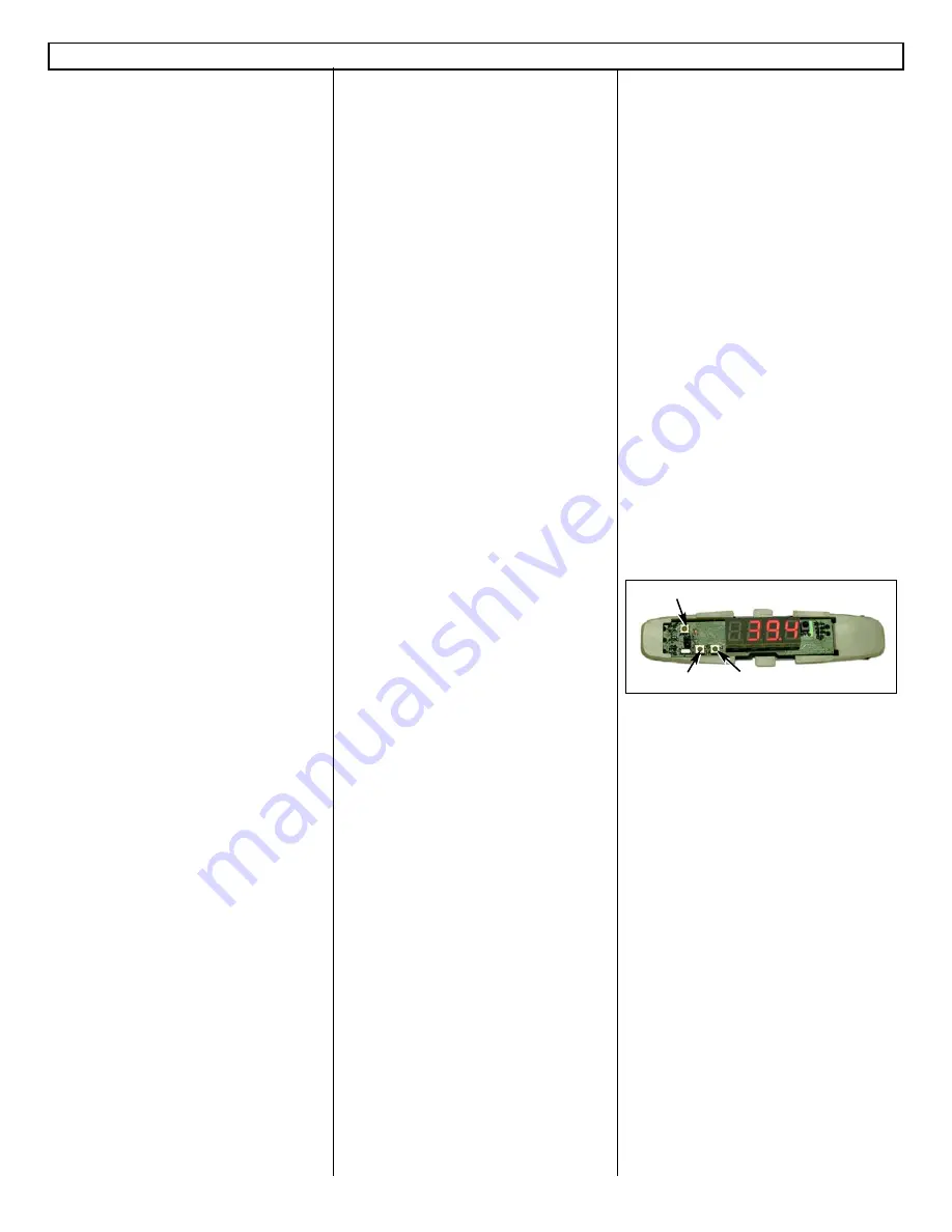
BUTTON ACTION
This photo identifies the buttons and the corresponding action on the
Safe-NET Display Module.
Safe-NET™ Self-contained Operating Instruction
Page
3 of 8 — P/N 0485005_B
www.hussmann.com/cstore/c_techinfo.htm
© 2007 Hussmann Corporation • Bridgeton, Missouri 63044-2483 U.S.A.
20 June 2007
SELECT Button
UP Button
Safe-NET™ Display Module Button Action
DOWN Button


