background image

REVISION HISTORY

REVISION

E

— 

JULY 2013

1. Included Night Curtain Installation Instructions

Page 1-5 and 1-6

REVISION

D

— 

FEBRUARY 2012

1. Changed NEMA plug

2. Removed Remote Case setup instructions

REVISION

C

— 

JANUARY 2012

1. Added LED Light Bars

2. Removed Remote Models

3. New Wiring Diagram SHM-3, SHM-4

REVISION B — 

DECEMBER 2010

1. Revised defrost settings, Page 3-3

2. Changed Defrost Frequency (2); Page 3-7

3. Revised defrost settings; Page A-3

ORIGINAL ISSUE — 

NOVEMBER 2010

vi

 * * * * * * * * * * * * * * * * * * * * * * * * * *

ANSI Z535.5 DEFINITIONS

• DANGER – 

Indicate[s] a hazardous

situation which, if  not avoided, will
result in death or serious injury.

• WARNING –

Indicate[s] a hazardous

situation which, if  not avoided, could
result in death or serious injury.

• CAUTION –

Indicate[s] a hazardous

situation which, if  not avoided, could
result in minor or moderate injury.

• NOTICE –

Not related to personal injury

Indicates[s] situations, which if  not avoided,
could result in damage to equipment.

P/N 0515258_E

U.S. & Canada 1-800-922-1919 • Mexico 01 800-890-2900 • www.hussmann.com

Summary of Contents for SHM

Page 1: ... SHM Medium Temperature Self Contained Specialty Horizontal Merchandiser Installation Service Manual P N 0515258_E July 2013 IMPORTANT Keep in store for future reference ...

Page 2: ......

Page 3: ...PORTANT KEEP IN STORE FOR FUTURE REFERENCE Quality that sets industry standards 12999 St Charles Rock Road Bridgeton MO 63044 2483 U S Canada 1 800 922 1919 Mexico 01 800 890 2900 www hussmann com 2013 Hussmann Corporation ...

Page 4: ......

Page 5: ...n Diagram 3 3 Temperature Adjustment 3 4 Alarms and Codes 3 4 Defrost Termination Switch 3 4 Manual Defrost 3 4 Full Cold and 1 Position 3 5 Sensor to Control Adjustment 3 6 Controls and Adjustments 3 7 Start Up 3 8 Load Limits 3 8 Stocking 3 8 Thermometer 3 8 MAINTENANCE Care and Cleaning 4 1 Do NOT Use 4 1 Do 4 1 Removing Scratches from Bumper 4 2 Cleaning Under Step Pan 4 2 Cleaning Discharge H...

Page 6: ...7 3 Revised defrost settings Page A 3 ORIGINAL ISSUE NOVEMBER 2010 vi ANSI Z535 5 DEFINITIONS DANGER Indicate s a hazardous situation which if not avoided will result in death or serious injury WARNING Indicate s a hazardous situation which if not avoided could result in death or serious injury CAUTION Indicate s a hazardous situation which if not avoided could result in minor or moderate injury N...

Page 7: ...en carefully inspected at our factory Any claim for loss or damage must be made to the carrier The car rier will provide any necessary inspection reports and or claim forms Apparent Loss or Damage If there is an obvious loss or damage it must be noted on the freight bill or express receipt and signed by the carrier s agent otherwise carrier may refuse claim Concealed Loss or Damage When loss or da...

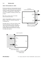
Page 8: ...E SURE TO POSITION SELF CONTAINED MERCHANDISERS PROPERLY SELF CONTAINED models have vented base panels to allow air circulation through the condensing unit See illustrations for clearances distances from walls merchandisers and any other large objects near the merchandiser s vented base panels Blocking or restricting air flow will adversely affect performance and may damage the refrigeration syste...

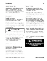
Page 9: ...ERNAL LOADING such as the weight of a person Do not place heavy objects on the merchandiser SHIPPING SKID Each merchandiser is shipped on a skid to protect the merchandiser s base and to make positioning the case easier Do not remove the shipping skid until the merchandiser is near its final location The skid provides protection for both the merchandiser and the floor Remove the skid by raising on...

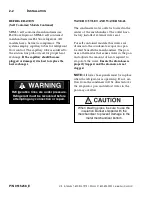
Page 10: ...straight upward and over the screws on which it is hanging The panel is installed by reversing the above procedure Ensure lower access panel is flat against the floor when installed to prevent air circulation problems on self contained merchandisers Safe NET III display is mounted on left side of access panel Be careful not to detach Safe NET III cable from display when removing access panel SEALI...

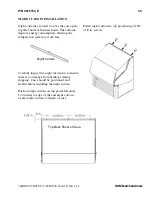
Page 11: ... curtain kit to ensure there is no damage from breakage during shipping Case should be positioned and leveled before installing the night curtain Position night curtain on top panel Measure 1 50 inches to edge of the end night curtain Center night curtain to length of case Fasten night curtain to top panel using 3 8 x 1 2 in screws HUSSMANN CORPORATION BRIDGETON MO 63044 2483 U S A SHM Merchandise...

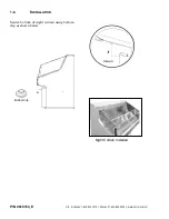
Page 12: ... INSTALLATION Secure bottom of night curtain using bottom clip as shown below P N 0515154_E U S Canada 1 800 922 1919 Mexico 01 800 890 2900 www hussmann com Detail A A Night Curtain Installed Bottom Clip ...

Page 13: ...rcuit Always use a dedicated circuit with the amperage stated on the unit Plug into an outlet designed for the plug Do not overload the circuit Do not use long or thin extension cords Never use adapters If in doubt call an electrician Self contained models have factory installed power cords attached at the electrical box REFRIGERATION Self Contained Models Each self contained model is equipped wit...

Page 14: ...he merchandiser The outlet has a factory installed external water seal For self contained models this water seal drains into the condensate evaporator pan located beneath the merchandiser The pan uses a thermistor that senses water in the pan and adjusts the amount of heat required to evaporate the water Ensure the drain hose is properly trapped and the drain area is not clogged NOTE All lower bas...

Page 15: ...temperature and defrost control for your chilled or frozen food The front of the controller has an adjustment knob and status LEDs The back of the controller has connections for sensors and switched equipment The Safe NET III controller includes the following features and connections Adjustment knob Adjusts the temperature setpoint Turn adjustment knob to OFF to turn off refrigeration system Unplu...

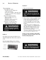
Page 16: ... on the controller START UP 1 Plug in the merchandiser 2 Wait for the self check to complete During the self check each LED flashes for one second then all LEDs turn on for two seconds If the LEDs do not flash make sure the adjustment knob is not in the Off position After the self check all LEDs turn off until the compressor starts There may be a delay before the compressor starts If the red Tempe...

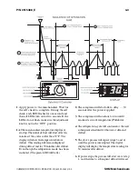
Page 17: ...efore defrost This reading will remain displayed during defrost and for 50 minutes after defrost Even though the refrigeration mode has been initiated The green LED will be lit 2 The compressor will start after a delay 30 seconds after the power is applied 3 The compressor will continue to run until it reaches its cut out temperature Pulldown 4 The refrigeration cycle will continue for the next su...

Page 18: ... Alarm LED red on the controller and display is flashing a temperature sensor has failed The display shows E1 if the case sensor has failed or E2 if the evaporator sensor has failed If the merchandiser sensor fails refrigeration will run continuously Turn off or repeat a duty cycle of a few minutes on and a few minutes off DEFROST TERMINATION SWITCH Merchandisers may use a defrost termination swit...

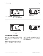
Page 19: ...Rotate the adjustment knob counter clockwise for a warmer setpoint or clockwise for a colder setpoint While the temperature is being adjusted the optional display shows the setpoint cut out value A few seconds after the temperature is set the display reverts to showing the sensed temperature in the merchandiser ...

Page 20: ...3 6 START UP OPERATION P N 0515388_E U S Canada 1 800 922 1919 Mexico 01 800 890 2900 www hussmann com ...

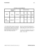
Page 21: ...panel Adjust this control knob to maintain the discharge air temperature shown Measure discharge air temperatures at the center of the discharge honeycomb Defrosts are time initiated and temperature terminated for self contained and remote The defrost setting is factory set as shown above To ensure a thorough defrost defrost must be terminated by the temperature termination setting not by time ...

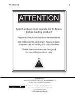
Page 22: ...NG Product should NOT be placed inside the merchandisers until merchandisers are at proper operating temperature Allow merchandiser 24 hours to operate before loading product Proper rotation of product during stocking is necessary to prevent product loss Always bring the oldest product to the front and set the newest to the back AIR DISCHARGE AND RETURN FLUES MUST REMAIN OPEN AND FREE OF OBSTRUCTI...

Page 23: ...interior surfaces Do not use high pressure water hoses Do Remove the product and all loose debris to avoid clogging the waste outlet Store product in a refrigerated area such as a cooler Remove only as much product as can be taken to the cooler in a timely manner Disconnect electrical power before cleaning Thoroughly clean all surfaces with soap and hot water DO NOT USE STEAM OR HIGH WATER PRESSUR...

Page 24: ... as this may cause pitting and rusting of the stainless steel finish Do not use bleach CLEANING UNDER STEP PAN Remove all product from the merchandiser and place in cooler Always disconnect electrical power before cleaning 1 Place a small screw driver between the front grille and step pan Gently lift the step pan s front lip up Grasp the step pan with both hands to remove Always wear gloves when r...

Page 25: ... needed depending on the operational environ ment A dirty condenser blocks normal airflow through the coils Airflow blockage increases energy consump tion and reduces the merchandiser s ability to maintain operating temperature To clean the coils use a vacuum cleaner with a wand attachment and a soft non metallic brush to remove dirt and debris Do not bend coil fins Always wear gloves and protecti...

Page 26: ...eater is not properly operating Remove accumulated debris from the evapora tion pan Wipe down heater coil with a cloth and warm water Be sure to remove any dirt debris or liquids from the heater coil Water introduced during cleaning will cause the evaporation pan to overflow REMOVING SCRATCHES FROM BUMPER Most scratches and dings can be removed using the following procedure 1 Use steel wool to smo...

Page 27: ...laced remove fan motor brackets from the fan plenum as shown 7 Replace fan motor and or blades 8 Install brackets to fan motor and install motor and bracket to the plenum 9 Reconnect fan motor to wiring harness 10 Turn on power 11 Verify that motor is working and blade is turning in the correct direction 12 Reinstall display pans Bring merchandiser to operating temperature before restocking SERVIC...

Page 28: ... prongs on the replace ment bulb twist and lock into place REPLACING BALLAST POWER SUPPLY LED fixture replacement follows the same steps as fluorescent bulbs However LED fixtures have the sleeve built in as a single assembly The LED power supply is also located in the condensing unit electrical box Fluorescent lamps contain mercury vapor Mercury exposure at high levels can harm the brain heart kid...

Page 29: ...e Pan OPTIONAL LIGHT BAR TP 4482388 Light Bar Fluorescent SHM 3 TP 4482391 Light Bar Fluorescent SHM 4 BU 4441801 LED Fixture for Light Bar SHM 3 BU 4441800 LED Fixture for Light Bar SHM 4 Item Part Description CONTROL PANEL SW 4440546 Disconnect Switch 25Amps CC 4481520 Compressor Relay SW 4441070 Pressure Control REFRIGERATION EQ 4671186 Condensing Unit Assembly SHM 3 EQ 4671183 Condensing Unit ...

Page 30: ...e back to front 43 1 2 1105 87 2210 Note Includes bumper Width of skid rail 9 5 8 244 19 1 4 488 Waste Outlet LH end of case from outside of End Assembly 33 1 2 851 67 1702 to center of waste outlet P N 0515154_E U S Canada 1 800 922 1919 Mexico 01 800 890 2900 www hussmann com A 2 APPENDIX A TECHNICAL DATA MODEL SHM300 18 36 SHM400 24 48 SHM ...

Page 31: ...unless otherwise stat ed Schedule defrost at night while lights are off SHM SHM 3 SHM 4 Thermostat Setting CI CO F Position 1 37 30 37 30 Position 7 37 14 37 14 Condensing Unit hp 1 3 1 2 Condensing Unit Capacity 2300 3535 Btu hr at std rating conditions DEFROST DATA Frequency hr 12 OFFTIME Failsafe minutes 45 Defrost Termination Temperature 52ºF PHYSICAL DATA Refrigerant Charge SHM 3 27 5 oz 1 36...

Page 32: ...V 3 350 Condensing Unit 208 230V 1Ph 60Hz Standard SHM 3 Compressor LRA 39 0 Compressor RLA 7 9 SHM 4 Compressor LRA 48 0 Compressor RLA 9 5 Product Data ARI Total Display Area 1 Sq Ft Case SHM 3 6 29 ft2 case 0 584 m2 case SHM 4 8 42 ft2 case 0 782 m2 case 1 Computed using ARI 1200 standard methodology Total Display Area ft2 m2 Unit of Length ft m A 4 APPENDIX A TECHNICAL DATA P N 0515154_E U S C...

Page 33: ... BRIDGETON MO 63044 2483 U S A SHM Merchandisers ESTIMATED SHIPPING WEIGHT 2 Case SHM 3 SHM 4 End lb kg 350 158 310 140 Included 2 Actual weights will vary according to optional kits included APPENDIX A TECHNICAL DATA A 5 ...

Page 34: ...P N 0515154_E U S Canada 1 800 922 1919 Mexico 01 800 890 2900 www hussmann com A 6 APPENDIX A WIRING DIAGRAM SHM 3 SHM 4 SHM 4BW SELF CONTAINED ...

Page 35: ... information or other support contact your Hussmann representative Please include the model and serial number of the product Hussmann Corporation Corporate Headquarters Bridgeton Missouri U S A 63044 2483 01 October 2012 ...

Page 36: ...Hussmann Corporation 12999 St Charles Rock Road Bridgeton MO 63044 2483 www hussmann com ...

Reviews: