background image

IGSSB-SHVSS-0302

6

REFRIGERATION

Unless otherwise specified on the factory order, remote
and self-contained merchandisers are equipped for
operation on R134A refrigerant. The correct type of
refrigerant will be stamped on each merchandiser’s serial
plate located inside the merchandiser.

Refrigerant Piping
Connection Sizes:

Liquid Line

1/4” OD

Suction Line

3/8” OD

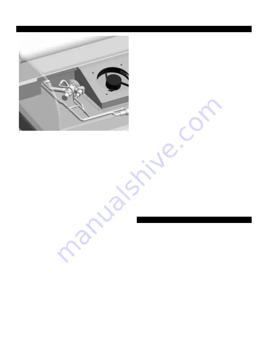
The refrigerant line connections are behind the rear
close-off panel, underneath the drain tub, on the left
hand end of the merchandiser as viewed from the rear.

After connections have been made, seal this outlet
thoroughly. Seal both inside and the outside. We recom-
mend using an aerosol dispensed urethane type of
insulation.Case specification section in the back of the
book for proper duration and frequency. Self contained
cases have individual defrost time clocks. When power
has been applied, set the time clock to the proper
duration and frequency.
The time clock is located behind the front panel under
the case. Turn the clock dial counterclockwise until the
pointer is directed to the current time of day.

Multiplexing - Piping of merchandisers operating on
the same refrigeration system may be run from merchan-
diser to merchandiser through the end frame saddles
provided for this purpose. DO NOT RUN REFRIG-
ERANT LINES THROUGH MERCHANDISERS
THAT ARE NOT THE SAME REFRIGERATION
SYSTEM
 as this may result in poor refrigeration
control and compressor failure.

Line Sizing - Refrigerant lines should be sized as shown
on the refrigeration legend that is furnished for the store
(not furnished by Hussmann). If a legend has not been
furnished, refer to the Hussmann Application Engineering
Manual for guidance.

Oil Traps - P-traps (oil traps) must be installed at the
base of all suction line vertical risers.

Pressure Drop - Pressure drop can rob the system of
capacity. To keep the pressure drop to a minimum, keep
the refrigerant line run as short as possible using a
minimum number of elbows. Where elbows are required,
use long radius elbows only.

Insulation - The suction and liquid lines should be
clamped or taped together and insulated for a minimum
of 30’ from the merchandiser. Additional insulation is
recommended wherever condensation drippage is
objectionable.

CONTROLS AND ADJUSTMENTS

The objective of the controls and settings listed in this
section is to maximize product shelf life. Not complying
with these instructions will increase spoilage rate due to
drying of the product and could cause sweating on the
front glass if operated too cold.

Allow bakery products to reach store ambient condi-
tions after preparation just prior to display. This is
essential to maximize the shelf life of perishables.

Summary of Contents for SHVSS

Page 1: ... Chino SHVSS Summit High Volume Self Service Bakery Case REV 0302 Installation Operation Manual SHVSS Summit High Volume Self Service Bakery Case P N IGSSB SHVSS 0302 INSTALLATION OPERATION GUIDE ...

Page 2: ... When loss or damage is not apparent until after equipment is uncrated a claim for concealed damage is made Make request in writing to carrier for inspection within 15 days and retain all packaging The carrier will supply inspection report and required claim forms SHORTAGES Check your shipment for any possible shortages of material If a shortage should exist and is found to be the responsibility o...

Page 3: ... not set temperature too cold as this causes product dehydration Temperatures should be achieved by a t stat and suc tion solenoid at each case Do not use EPR valves liq uid line solenoids or electronic control devices of any kind These controls allow temperature swings causing product dehydration and excessive energy consumption Defrost cycles should be set according to the Case Specifications in...

Page 4: ...hich means that two or more may be joined in line yielding one long continuous display requiring only one pair of ends Joint kits and instructions are shipped separately ACES SHIPPING BRACES NOT ALL MERCHANDISERS Move the fixture as close as possible to its permanent location and then remove all packaging Check for damage before discarding packaging Remove all sepa rately packed accessories such a...

Page 5: ...diam eter of the pipe or water seal supplied with the mer chandiser 2 When connecting drip piping the water seal must be used as part of the drip piping to prevent air leakage or insect entrance Never use two water seals in series in any one drip pipe Double water seals in series will cause an air lock and prevent draining 3 Pitch the drip piping in the direction of flow There should be a minimum ...

Page 6: ...s provided for this purpose DO NOT RUN REFRIG ERANT LINESTHROUGH MERCHANDISERS THAT ARE NOTTHE SAME REFRIGERATION SYSTEM as this may result in poor refrigeration control and compressor failure Line Sizing Refrigerant lines should be sized as shown on the refrigeration legend that is furnished for the store not furnished by Hussmann If a legend has not been furnished refer to the Hussmann Applicati...

Page 7: ... 3 50 In 1 2 115 18 0 Air 2 6 30Out 5 4300 20 40 30 225 Opt Forced 4 1 2 36 min 28 1 12 3 50 In 1 2 115 18 0 Air 2 6 30Out 6 5160 20 40 30 225 Opt Forced 4 1 2 36 min 42 3 36 3 50 In 3 4 115 18 5 Air 3 30Out NOTES These refrigerated merchandisers have been designed for use in stores where temperatures and humidity are maintained at or below 75 F and 55 RH Stores are responsible for setting their c...

Page 8: ...t in personal injury Allow glass fronts ends and service doors to warm before applying hot water Exterior Surfaces The exterior surfaces must be cleaned with a mild detergent and warm water to protect and maintain their attractive finish Never use abrasive cleansers or scouring pads Front Glass DO NOT use the front glass as a support during cleaning Removal of the glass is NOT recommended Interior...

Page 9: ...l wiring must be in compliance with NEC and local codes All electrical connections for the nonrefrigerated model are to be made in the electrical panel Electrical connections for refrigerated models are made in the electrical box on the back of the case behind the rear close off panel Field Wiring Field wiring must be sized for compo nents amperes stamped on the serial plate Actual ampere draw may...

Page 10: ...essure Safety 115V 1Ø 60 Hz 20A Compressor Motor 115V 3 4HP 11A RLA Start Capacitor Condensing Fan black yellow 8045 00 120V 125 01 0710 Paragon Timer S C T X 4 N 3 1 2 S R 3 1 2 C MOTOR 5 2 1 1 3 2 1 3 Control Panel J BOX red black yellow black T Stat Start Capacitor Run Capacitor red blue black red C R T X 4 N 3 1 S R 3 1 2 C MOTOR 5 2 1 MagneTek B 332i120RH blue blue 1 3 2 1 3 2 2 2 1 3 2 1 3 r...

Page 11: ...3 4HP 6 7A RLA Condensing Fan Paragon Timer T X 4 N 3 1 2 S R 3 5 2 1 1 3 2 1 3 J Panel J BOX 12 black T Stat red T N 1 1 2 C MOTOR MagneTek B 332i120RH blue blue 1 3 2 1 3 2 2 2 1 3 2 1 3 red 3 Pins male harness red red Cap LIGHTS Cap F40T8 SPX35 F40T8 SPX35 F40T8 SPX35 1 2 3 Crown Light hard wiring Shelves Lights 3 Pins male harness 3 Pins male harness M M M 2 wires Female harness 3 12 black 12 ...

Page 12: ...up evaluation prior to the loading of food into the refrig erator which includes such items as a Initial temperature performance Coils should be properly fed with a refrigerant according to Hussmann s recommendations b Observation of outside influences such as drafts radiant heating from the ceiling and from lamps Such influence should be properly corrected or compensated for c At the same time ch...

Page 13: ...e evaporator fan motor blade inoperative 14 Is the defrost time excessive 15 Is the defrost termination thermostat if used set too high 16 Are the refrigerant controls incorrectly adjusted 17 Is the air entering the condenser above design condi tions Are the condenser fins clear of dirt dust etc 18 Is there a shortage of refrigerant 19 Has the equipment been modified to use replacements for CFC 12...

Page 14: ...a tion h Keep tools clean and sanitized Since mechanical equipment is used for fresh meat processing all suchequipmentshouldbecleanedatleastdailyand each time a different kind of meat product comes in contact with the tool or equipment i Make sure that all refrigeration equipment is in stalled and adjusted in strict accordance with Hussmann s recommendations j See that all storage and refrigeratio...

Page 15: ...under this warranty shall be limited to a period not to exceed five years from date of factory shipment On Hussmann refrigeration systems an additional 4 year extended warranty for the motor compressor assem bly is available but must be purchased prior to shipment to be in effect Hussmann reserves the right to inspect the job site installation and reason for failure The motor compressor warranties...

Page 16: ...articular unit They can be found on a small metal plate on the unit Please note them below for future reference MODEL SERIAL NUMBER Chino Additional copies of thispublication may be obtained by contacting Hussmann Chino 13770 RamonaAvenue Chino California 91710 909 628 8942 FAX 909 590 4910 800 395 9229 Service Record Last service date By ...

Reviews: