background image

12

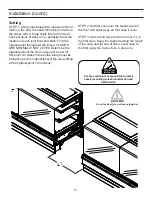
STEP 4. Apply liberal bead of case joint sealant 

(Silicone) to fi rst case. Sealant area is shown in 
illustration. Apply heavy amount to cover entire 
shaded area. (pg10) 
STEP 5. Slide second case up to fi rst case 
snugly. Then level second case to the fi rst case 
so glass front, bumper and top are fl ush.

Installation (Cont’d)

STEP 6. To compress butyl at joint, use two 
Jurgenson wood clamps. Make sure case is 
level from front to back and side to side on inside 
bulkheads at joint.
STEP 7. Attach sections together using bolting 
locations.

Summary of Contents for SHVSV Series

Page 1: ... SPECIALTY U S E R M A N U A L 032018 MERCHANDISER SHVSV BAKERY SERVICE SHVSV SHVSV DWR 3 R SHVSV DWR 4 R SHVSV DWR 8 R SHVSV DWR 10 R SHVSV DWR 45IS R Remote ...

Page 2: ...Sheet 17 Electrical 18 Merchandiser Electrical Data 18 Electrical Connections 18 Field Wiring 18 Identification of Wiring 18 Remove Rear Raceway 19 Electrical Conduit Electrical Box 19 Electrical Wiring Diagram 20 DOE 2012 Energy Efficiency Compliant Hussmann refrigerated merchandisers configured for sale for use in the United States meet or surpass the requirements of the DOE 2012 energy efficienc...

Page 3: ...smann Chino If such a shortage involves the carrier notify the carrier immediately and request an inspection Hussmann Chino will acknowledge shortages within ten days from receipt of equipment Hussmann Chino Product Control The serial number and shipping date of all equipment have been recorded in Hussmann s files for warranty and replacement part purposes All correspondence pertaining to warranty ...

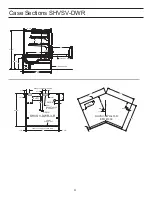
Page 4: ...5 1 8 1 3 8 3 1 2 6 3 1 8 20 38 1 2 1 1 8 1 1 8 36 REFRIG 4 8 GFCI RECEPTACLES OPTIONAL SHVSV DWR 3 R L C 1 3 8 3 1 2 REAR OF CASE SERVER SIDE FRONT OF CASE CUSTOMER SIDE DRAIN ELECT FRONT CLOSE OFF Elect Refrig Drain 8 4 L C 20 4 1 8 6 3 1 8 38 1 2 39 7 8 39 7 8 SHVSV DWR 45I R EFR 1338 2 Case Sections SHVSV DWR ...

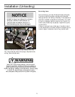
Page 5: ...ng damage before and during unloading This equipment has been carefully inspected at our factory Any claim for loss or damage must be made to the carrier The carrier will provide any necessary inspection reports or claim form If there is obvious loss or damage it must be noted on the freight bill or express receipt and signed by the carrier s agent otherwise carrier may refuse claim Glass can caus...

Page 6: ...5 The SHVSV merchandiser can be raised at one end underneath the deck with a forklift or J Bar if forklift is not accesible to allow the placement of rollers or dollies 6 Evenly support the entire base structure on rollers or dollies before attempting to move Each Base Leg must have its own dollie to properly support the case WARNING Improper placement of forks may damage drainage piping Use a spo...

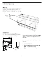
Page 7: ...es perfect place ment of a dollie per 1 side for both base legs of the merchandiser IF APPLICABLE NOT ALL CASES CARRY LEG BRACES Move the fixture as close as possible to its perma nent location and then remove all packaging and prepare to remove off Skid Remove all separately packed accessories such as kits and panels Check for damage before discarding packaging Installation Cont d Hardware Removal...

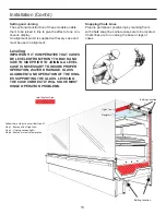
Page 8: ...Adjust the legs at each corner of the case to level out any discrepancies in order to optimize case performance and proper drainage A Levelling Bolt Lock Nut Note To avoid removing concrete flooring begin line up levelling from the highest point of the store floor A wrench or pliers may be used to adjust each base leg Loosen the lock nut Turn the levelling bolt to raise or lower the height of the ca...

Page 9: ...9 Joint Trim Pack list ...

Page 10: ...ECESSARY TO INSURE PROPER OPERATION WATER DRAINAGE GLASS ALIGNMENT AND OPERATION OF THE HING ES SUPPORTING THE GLASS LEVELING THE CASE CORRECTLY WILL SOLVE MOST HINGE OPERATION PROBLEMS Bolting Location Joint Sealant Area Bolting Location Follow these steps to access Bolt Loc 1 Step 1 Remove front light can Step 2 Unplug canopy lights Step 3 Remove screw to lower plex 1 2 3 4 Light Can Plexiglass ...

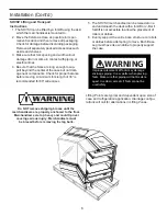
Page 11: ... set off this point All cases in the entire lineup must be brought up to the highest level of the case sitting at the highest point in the lineup 1 Do not use bolts to pull cases together It is the contractor s responsibility to install case s according to local construction and health codes ATTENTION INSTALLER STEP 2 Set first case over the highest part of the floor and adjust legs so that case is ...

Page 12: ...pg10 STEP 5 Slide second case up to first case snugly Then level second case to the first case so glass front bumper and top are flush Installation Cont d STEP 6 To compress butyl at joint use two Jurgenson wood clamps Make sure case is level from front to back and side to side on inside bulkheads at joint STEP 7 Attach sections together using bolting locations ...

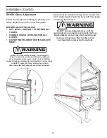
Page 13: ... adjacent glass simultaneously could result in but not limited to glass breakage damage to merchandiser serious injury or death To prevent injury when glass is open take adequate safety measures to protect shoppers Glass must be parallel to ledge when viewed from front Glass height should be level with front ledge as demonstrated below Do NOT remove shipping braces until the merchandisers are prop...

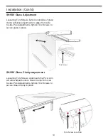
Page 14: ...o glass from side to side Post adjustments tighten Torx Screws to secure glass in place SHVSV Glass Clamp Adjustment Loosening Torx Screws underneath the Pivot Arm will allow adjustments to Glass Clamp from side to side Post adjustments tighten Torx Screws to secure Glass Clamp in place A A Torx Screws A Torx Screw Location ...

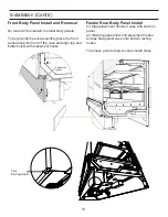
Page 15: ...nd lay flat against case onto bottom resting hooks To remove panel simply reverse install steps Front Body Panel Install and Removal No tools will be needed to install body panels To begin bottom panel assembly place the front panel along the front of the case and align top and bottom slots with placement hooks A 2 1 Placement Hooks A Case Resting Hooks ...

Page 16: ...g The refrigerant line connections are at the right hand end of the case as viewed from the front beneath the display pans The merchandiser will beforehand ensure an earlier cut hole through the pod to exit the merchandiser for the refrigera tion lines After connections have been made make certain to seal this outlet thoroughly if not sealed at factory already Seal both the inside and outside We r...

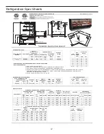
Page 17: ...AL HIGH OUTPUT LED LIGHTS 115 VOLT DRAWERS AMPS WATTS AMPS WATTS AMPS WATTS 3 0 32 37 0 29 34 0 61 70 3 4 0 41 47 0 35 41 0 76 88 4 5 N A N A N A N A N A N A 5 6 0 64 73 0 59 67 1 22 141 6 8 0 82 94 0 71 81 1 53 176 8 10 N A N A N A N A N A N A 10 12 1 23 141 1 06 122 2 29 264 12 45 IS N A N A N A N A N A N A 45 IS 3 2 1 1 2 2 2 CASE LENGTH NUMBER OF DRAWERS 1 AMPS WATTS OUTLETS VOLTS AMPS WATTS A...

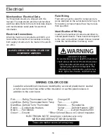
Page 18: ...ticker shown below located inside the merchandiser s wireway cover WARNING LOCK OUT TAG OUT To avoid serious injury or death from electrical shock always disconnect the electrical power at the main disconnect when servicing or replacing any electrical component This includes but is not limited to such items as doors lights fans heaters and thermostats Leads for all electrical circuits are identifi...

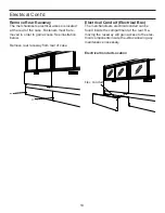
Page 19: ...gain access See illustration below Remove rear raceway from rear of case Electrical Conduit Electrical Box The merchandisers electrical conduit can be found inside the compartment at the rear Re moving the raceway will gain access to the elec trical components inside the J Box allowing any maintenance necessary Electrical Conduit Location Elec Conduit ...

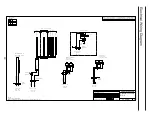
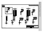
Page 20: ...20 Electrical Wiring Diagram 0 0 0 1 0 0 0 0 2 0 0 3 0 0 1 1 1 1 1 ...

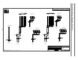
Page 21: ...21 Electrical Wiring Diagram Cont d 0 1 1 1 2 0 1 1 0 1 1 3 0 1 1 4 0 1 1 2 2 2 2 ...

Page 22: ...22 0 1 2 2 2 3 0 1 2 2 0 1 2 2 3 3 3 0 1 2 2 4 0 1 2 2 0 1 2 2 3 0 1 2 2 2 3 3 3 3 3 Electrical Wiring Diagram Cont d ...

Page 23: ...23 0 0 0 1 2 0 0 0 0 0 0 345 0 0 0 0 6 0 0 2 2 2 2 2 2 2 2 2 0 0 0 1 Electrical Wiring Diagram Cont d ...

Page 24: ...24 0 1 1 1 2 0 1 1 0 1 1 2 3 0 1 1 4 0 1 1 2 2 2 2 2 2 2 2 Electrical Wiring Diagram Cont d ...

Page 25: ...ervicing or replacing any electrical component This includes but is not limited to such items as doors lights fans heaters and thermostats Case Switches Light switches for the merchandiser are located inside the case near the rear arm structures See illustration below Load Limit Line DO NOT LOAD PAST THE FOLLOWING LOAD LIMIT LINES Load Limit Each Merchandiser has a load limit Shelf life of perisha...

Page 26: ...ess steel finish Do not use bleach Clean frequently to avoid build up of hard stub born stains A stainless steel cleaning solution may be used periodically to minimize scratching and remove stains Rinse and wipe dry immediately after cleaning Never use hydrochloric acid muriatic acid on stainless steel Interior Surfaces The interior surfaces may be cleaned with most domestic detergents ammonia base...

Page 27: ...igh pressure water hoses to wash the interior These will destroy the merchandisers sealing causing leaks and poor performance Avoid direct contact between fan motors and cleaning or rinse water Rinse with hot water but DO NOT flood Never introduce water faster than the waste outlet can drain Allow merchandiser to completely dry before resuming operation LED lights are magnetized to each shelf and c...

Page 28: ...ed make sure debris is not blocking the intake section Coil close offs are not installed Inspect coil to make sure these parts are on the case Condensing coil or evaporator coil is clogged or dirty Clean coil Case temperature is too cold The t stat temp is set too low Check settings See Technical Specifications section Ambient conditions may be affecting the case operation Check case position in st...

Page 29: ...ap is clogged Clear any debris Frost or ice on evaporator coil Evaporator fans are not functioning Check electrical connections Defrost clock is not functioning Case should be serviced by a qualified service technician Coil is freezing over Return air is blocked make sure debris is not blocking the intake section Coil close offs are not installed Inspect coil to make sure these parts are on the cas...

Page 30: ...red more of a right to know law than a pure product safety law When used as designed Hussmann believes that our products are not harmful We provide the Proposition 65 warning to stay in compliance with California State law It is your responsibility to provide accurate Proposition 65 warning labels to your customers when necessary For more information on Proposition 65 please visit the California S...

Page 31: ... other support contact your Hussmann representative Please include the model and serial number of the product Hussmann Corporation Corporate Headquarters Bridgeton Missouri 63044 2014 Hussmann Warranty Technical Assistance 800 592 2060 ...

Reviews: