18
Electrical
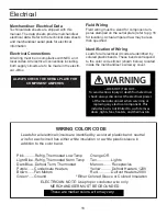
Merchandiser Electrical Data
Technical data sheets are shipped with this
manual. The data sheets provide merchandiser
electrical data. Refer to the technical data sheets
and merchandiser serial plate for electrical
information.
Electrical Connections
All wiring must be in compliance with NEC and
local codes. All electrical connections including
both supply circuits are to be made in the electri-
cal J-Box.
ALWAYS CHECK THE SERIAL PLATE FOR
COMPONENT AMPERES
Field Wiring
Field wiring must be sized for component am-
peres stamped on the serial plate (refer to pg 16
for location). Actual ampere draw may be less
than specifi ed.
Identifi cation of Wiring
Leads for all electrical circuits are identifi ed by
colored plastic bands. These bands correspond
to the color code sticker (shown below) located
inside the merchandiser’s wireway cover.
WARNING
--LOCK OUT/ TAG OUT--
To avoid serious injury or death from electrical
shock, always disconnect the electrical power
at the main disconnect when servicing or
replacing any electrical component. This
includes, but is not limited to, such items as
doors, lights, fans, heaters, and thermostats.
Leads for all electrical circuits are identified by a colored plastic band: neutral
wire for each circuit has either white insulation or a white plastic sleeve in
addition to the color band.
WIRING COLOR CODE
Pink...........Refrig, Thermostat Low Temp
Light Blue..Refrig, Thermostat Norm Temp
Dark Blue..Defrost Term, Thermostat
Purple.......Condensate Heaters
Brown.......Fan Motors
Green*......Ground
Orange OR
Tan...............Lights
Maroon........ Receptacles
Yellow.......... Defrost Heaters 120V
Red..............Defrost Heaters 208V
*Either Colored Sleeve or Colored Insulation
ELECTRICIAN NOTE: Use proper conductor wire only.
MERCHANDISER MUST BE GROUNDED
These are marker colors, wire may vary.
Summary of Contents for SHVSV Series
Page 9: ...9 Joint Trim Pack list ...
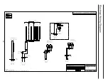
Page 20: ...20 Electrical Wiring Diagram 0 0 0 1 0 0 0 0 2 0 0 3 0 0 1 1 1 1 1 ...
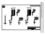
Page 21: ...21 Electrical Wiring Diagram Cont d 0 1 1 1 2 0 1 1 0 1 1 3 0 1 1 4 0 1 1 2 2 2 2 ...
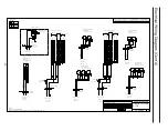
Page 24: ...24 0 1 1 1 2 0 1 1 0 1 1 2 3 0 1 1 4 0 1 1 2 2 2 2 2 2 2 2 Electrical Wiring Diagram Cont d ...

