background image

32


M

aIntEnancE

P/N 3034041_D 

U.S. & Canada 1-800-922-1919 • Mexico 1-800-890-2900 • www.hussmann.com

NOTES:

Summary of Contents for VRM1B

Page 1: ...e circulated by the fans If propane gas is present or even suspected do not allow untrained personnel to attempt to find the cause The propane gas used in the unit has no odor The lack of smell does not indicate a lack of escaped gas If a leak is detected immediately evacuate all persons from the store and contact the local fire department to advise them that a propane leak has occurred Do not let a...

Page 2: ...e fans If R 290 propane is present or even suspected do not allow untrained personnel to attempt to find the cause The propane gas used in the unit has no odor The lack of smell does not indicate a lack of escaped gas If a leak is detected immediately evacuate all persons from the store and contact the local fire department to advise them that a pro pane leak has occurred Do not let any persons ba...

Page 3: ...Rock Road Bridgeton MO 63044 2483 U S Canada 1 800 922 1919 Mexico 1 800 890 2900 www hussmann com 2018 Hussmann Corporation Merchandiser must operate for 24 hours before loading product Regularly check merchandiser temperatures Do not break the cold chain Keep products in cooler before loading into merchandiser These merchandisers are designed for only pre chilled products ATTENTION ...

Page 4: ... result in death or serious injury CAUTION Indicate s a hazardous situation which if not avoided could result in minor or moderate injury NOTICE Not related to personal injury Indicates s situations which if not avoided could result in damage to equipment Do NOT remove shipping crate until the merchandiser is positioned for installation Excessive ambient conditions may cause condensation and there...

Page 5: ...ly inspected at our factory Any claim for loss or damage must be made to the carrier The carrier will provide any necessary inspection reports and or claim forms Apparent Loss or Damage If there is an obvious loss or damage it must be noted on the freight bill or express receipt and signed by the carrier s agent otherwise carrier may refuse claim Concealed Loss or Damage When loss or damage is not...

Page 6: ...ct must be controlled to maximize the life of the product Be sure to position self contained merchandisers properly VRM models have vented base panels to allow air circulation through the condensing unit Allow for a minimum 36 in clearance in the front Blocking or restricting air flow will adversely affect performance and may damage the refrigeration system 36 in Rear arance d Rear e w Front Rear ...

Page 7: ... Lift crate from the skid Unscrew the case from the skid The merchandiser can now be lifted off the crate skid Lift only at base of skid Remove any braces and or skids attached blanket wrapped merchandiser may have skids DO NOT TILT MERCHANDISER ON ITS SIDE OR END WHEN REMOVING SKID Once the skid is removed the merchandiser must be lifted NOT PUSHED to reposition To remove the skid remove screws a...

Page 8: ...blies Magnetic door gaskets of one piece construction removable without tools for ease of cleaning Merchandiser can be placed against wall no air gap is required behind the case Digital display in center of case air grill CABINET LEVELING This merchandiser must be installed level from back to front and side to side to allow maximum draining of the condensate water as well as proper door alignment ...

Page 9: ... are adjustable Shelf spacing can be adjusted by positioning the shelf clips according to individual loading requirements VRM merchandisers have four movable wire shelves and one bottom wire shelf per door LAMPS This merchandiser has a light switch inside of the left door frame The switch controls the display lighting and interior lighting Shelves Bottom Shelf Light Switch ...

Page 10: ...packages signs etc to block air exhaust or return grille Do not use non approved shelving baskets display racks or any accessory that could hamper air curtain performance Do not stock product in the top four inches of VRM cases because product will block the cold air flow LOAD LIMITS Product must be within designated load limit to ensure proper refrigeration and air curtain performance Load Limit ...

Page 11: ...a safe place for future reference 2 Examine unit Confirm there is NO damage or concealed damage 3 Level the unit side to side and front to rear 4 Remove all shipping brackets compressor straps bolts etc 5 Unit must be run on a dedicated electrical circuit without the use of an extension cord 6 Ensure that the proper electrical requirements for the equipment are supplied 7 Verify field electrical c...

Page 12: ...12 Installation P N 3034041_D U S Canada 1 800 922 1919 Mexico 1 800 890 2900 www hussmann com NOTES ...

Page 13: ...ad the circuit Do not use long or thin extension cords Never use adapters If in doubt call an electrician VRL 1 VRL 2 VRMB 5 15P P 6 P 5 P LOCK OUT TAG OUT To avoid serious injury or death from electrical shock always disconnect the electrical power at the main disconnect when servicing or replacing any electrical component This includes but is not limited to such items as doors lights fans heater...

Page 14: ...propane equipment Failure to follow instructions can result in an explosion death injury and property damage If a leak is detected follow store safety procedures It is the store s responsibility to have a written safety procedure in place The safety procedure must comply with all applicable codes such as local fire department s codes At minimum the following actions are required Immediately evacuat...

Page 15: ...em with refrigerant to avoid the potential for static build up Extreme care must be taken not to overfill the refrigeration system After charging carefully disconnect the hoses attempting to minimize the quantity of refrigerant released Further leak check the service ports hoses refrigerant tanks The service ports shall be checked for leaks using a hydrocarbon leak detector with a sensitivity of 3 ...

Page 16: ...DGE P N 3033936 3 38 ROOF TO SENSOR 30 GAP BTW EDGE OF BASE AND SENSOR ROOF LINE 15 00 B B B B B Typical Sensor to Control Configuration 3032520 SENSOR AIR DISCHARGE FIX IN THE WALL VRM3B B DETAIL B SCALE 1 4 3 38 ROOF TO SENSOR 30 GAP BTW EDGE OF BASE AND SENSOR ROOF LINE 15 00 B B B 3032 SENSOR AIR DISCHARGE FIX IN THE WALL SENSOR DEFROST FIX IN THE SUCTION TUBE VRM3B B DETAIL B SCALE 1 4 3 08 R...

Page 17: ...X IN THE WALL FIX IN THE SUCTION LINE VRM1B NOTES 1 APPLICABLE STANDARDS SPECIFICATIONS ASME Y14 5M 1994 DIMENSIONS AND TOLERANCES 2 KEY PRODUCT CHARACTERISTICS PER EPR 0006 IDENTIFIED WITH SYMBOL 3 REF NONE K SHEET 3 P UNLESS OTHERW DIMENSIONS AR FIX IN THE SUCTION TUBE SENSOR DEFROST SENSOR AIR DISCHARGE FIX IN THE WALL VRL2B VRM2B C DETAIL C SCALE 1 2 67 ROOF LINE 15 00 EVAP BASE EDGE P N 30334...

Page 18: ...ature may reflect the refrigeration cycle of the Set Point and it s Differential The most accurate temperature on a cabinets operation is to verify the product temperature Taking as an example a VRL case freezer If the Set Point is 12 F and the Differential is 9 F Set Point 12 F 9 Differential 3 F The compressor and evaporator fan s will cycle off 12 F and back on at 3 F Main Features Panel mounte...

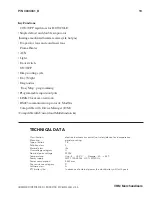
Page 19: ...ith Unicard and Multi function key 2 SPECIFICATIONS TECHNICAL DATA Classification electronic automatic control not safety device for incorporation Mounting panel mounting Type of action 1 B Pollution class 2 Material class IIIa Overvoltage category II Nominal pulse voltage 2500V Temperature Use 5 55 C Storage 30 85 C Power supply SMPS 100 240Va 10 50 60 Hz Power consumption 5 5W max Fire resistanc...

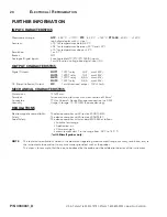
Page 20: ...40Va OUT2 1 SPDT relay 1HP max 250Va OUT3 1 SPDT relay 8 4 A max 250Va OUT4 1 SPST relay 8 4 A max 250Va OC Open Collector Output OC 1 multifunctional output 12Vc 20mA MECHANICAL CHARACTERISTICS Dimensions 121x92 mm Terminals faston and screw for wires with cross section of 2 5mm2 TTL for Unicard Device Manager connection via DMI Usage Storage 10 90 RH non condensing Connectors Humidity REGULATION...

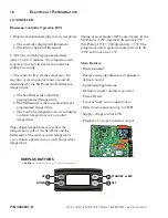
Page 21: ...KDEPlus or KDWPlus external keyboard or ECPlus echo module 3 LINE These are power supply terminals 19 18 PB1 probe connection 4 OUT2 Shared Terminal 21 20 PB2 probe connection 5 N O OUT2 23 22 PB3 probe connection 6 N C OUT2 23 24 PB4 probe connection 7 OUT3 Shared Terminal 23 25 PB5 probe connection 8 N C OUT3 27 26 Digital input DI 9 N O OUT3 28 29 LINK2 Connection 1 local area network 10 OUT1 S...

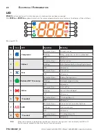
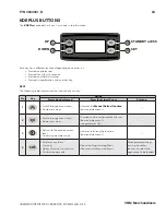
Page 22: ...t Permanently on Defrost active Blinking Activated manually or from Digital Input OFF otherwise 3 Fans Permanently on Fans active OFF otherwise 4 Reduced SET Economy Permanently on Energy Saving active Blinking Reduced setpoint active OFF otherwise 5 Alarm Permanently on alarm active Blinking Alarm acknowledged OFF otherwise 6 F readout Permanently on F setting dro 1 OFF otherwise 7 AUX Permanentl...

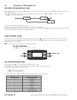
Page 23: ...n Pressed and released Press for at least 5 secs Start up 1 Scrolls through menu items Decreases values Activates the Manual Defrost function from outside menus 2 Scrolls through menu items Decreases values Function can be configured by the user from outside menus see parameter H32 3 Returns to the previous menu level Confirms parameter value Activates the Stand by function from outside menus 4 se...

Page 24: ... Key Action Pressed and released Press for at least 5 secs Start up 1 Scrolls through menu items Decreases values Activates the Manual Defrost function from outside menus 2 Scrolls through menu items Decreases values Function can be configured by the user from outside menus see parameter H32 3 Returns to the previous menu level Confirms parameter value Activates the Stand by function from outside ...

Page 25: ...ost domestic detergents and sanitizing solutions with no harm to the surface Always read and follow the manufacturer s instructions when using any cleaning product Inspect all LED connections and plug receptacles for signs of arcing Replace any component that shows signs of arcing Make sure all unused receptacles have close off covers securely attached CLEANING UNDERNEATH THE CASE The case can be ...

Page 26: ...rigeration then disconnect electrical power Remove product and loose debris Thoroughly clean all surfaces with soap and hot water Do not use steam or high water pressure hoses to wash the interior These destroy merchandiser s sealing causing leaks and poor performance Take care to minimize direct contact between fan motors and cleaning or rinse water Rinse with hot water but do NOT flood Allow mer...

Page 27: ...ondenser unit All VRM models have the same access panel design for commonality between merchandisers 1 Loosen screws at each side of the front bottom grille then lift up and pull off the grille 2 Next detach the merchandiser s electrical wire harness 3 Unscrew the stop bracket that holds the condensing unit to the rail base 4 Grab the condensing unit from condensing unit handle Use only the unit h...

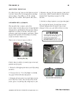
Page 28: ...vel Has the unit been moved recently 5 Shelves and Stocking Are the standard shelves in the correct places Is the product stocked properly Is the bottom shelf at the proper location 6 Confirm that the defrost schedule is properly set ADJUSTING CLOSING TORQUE Adjust closing torque by turning the bottom hinge pin in the direction the door closes Use a 1 2 in 13 mm wrench Turn the hinge pin until the...

Page 29: ...lashlight to identify any gaps between frame and gasket 3 Energize all anti sweat fan and light circuits for at least two hours but not more than four hours prior to initiating the refrigeration cycle 4 Monitor all gaps If gaps remain at the end of four hours follow the procedure for Restoring Gasket Seal beginning on page 6 of this manual 5 Initiate cooling sequence once gaps disappear Do not exc...

Page 30: ...orque cam socket assembly can cause excessive wear on the torque rod s spacer and sleeve bearing The result is a door that can seat farther down the rod assembly to the point that it causes binding at the hold open bracket It can also cause the top hinge pin s sleeve bearing to deform If the door is seated too far down the torque rod assembly it most likely damaged the top hinge pin sleeve bearing...

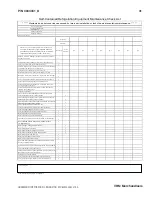
Page 31: ...and air registers fans and doors etc x Check for water leaks x Clean evaporator coil s and fan blade s Do not use an acid base cleaner Rinse off any cleaner residue x Clean discharge air honeycombs or grilles Do not use an acid base cleaner Rinse off any cleaner residue x Clean condenser coil s and fan blade s Do not use an acid base Cleaner Rinse off any cleaner residue x Clean condensate drain p...

Page 32: ...32 Maintenance P N 3034041_D U S Canada 1 800 922 1919 Mexico 1 800 890 2900 www hussmann com NOTES ...

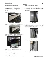
Page 33: ...fixture and LED power supply 5 Replace the LED with like fixture and re attach connection 6 Replace the display panel cover 7 Return power to the merchandiser REPLACING SHELF LAMPS 1 Disconnect power to the merchandiser The LED fixtures are located behind the top of the door frame 2 Remove the screws and disconnect the LED fixture from the merchandiser 3 Replace the LED with like fixture 4 Return ...

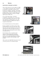
Page 34: ...er of the section up using putty knife only until the entire cover is off and the frame heater inside the door frame is exposed as shown in B Door frame heaters may now be replaced During installation the white portion of the heater should not come in contact with itself The heater should be installed so that only one white portion of the wire enters the raceway The other portion entering the race...

Page 35: ...on sparkling Component parts shall be replaced with identical components and servicing shall be done by factory authorized service personnel only so as to minimize the risk of possible ignition due to incorrect parts or improper service Visual Description of R290 Replacement Parts Main Switch Light Switch Solid State Relay 25 Amp Control Display KDE Control RTN400 Technical Data ...

Page 36: ...24 812 3041926 X Led Light CTR 4000K 3024564 X X Led Light RH 4000K 3024573 X X Door Black Med Temp LH 3025860 X X X Door Torsion Door Assy 3017256 X X X Door Gasket 3017271 X X X Door Handle 051007300 X X X Upper Lighted Display Part Number VRM1B VRM2B VRM3B White Plexiglass Display 1 Doors 3041296 X White Plexiglass Display 2 Doors 3020063 X White Plexiglass Display 3 Doors 3016789 X Power Suppl...

Page 37: ...024061 X X X Condenser Med Temp 3020001 X X X Condenser Fan Motor Assy 8 25 Motor Blade Brkt 3054705 X X X Evaporator Coil VRM1B 0534325 X Evaporator Coil VRM2B 0547180 X Evaporator Coil VRM3B 3025973 X Evaporator Fan Motor 1200 RPM 3055126 X X X Evaporator Fan Blade 8 25 3055130 X Evaporator Fan Blade 7 00 3055131 X X Evaporator Fan Motor Bracket 3058806 X X X Distributor Orifice 0 11 in 3020662 ...

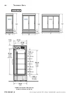
Page 38: ...38 Technical Data P N 3034041_D U S Canada 1 800 922 1919 Mexico 1 800 890 2900 www hussmann com Dimensions VRM Cross Section Dimensions shown as inches and mm ...

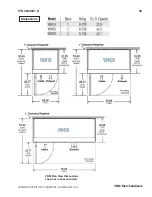
Page 39: ...P N 3034041_D 39 HUSSMANN CORPORATION BRIDGETON MO 63044 2483 U S A VRM Merchandisers Dimensions VRM Plan View Dimensions shown as inches and mm ...

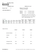
Page 40: ...em VRM1B 5 3 oz 0 150 kg 1 system VRM2B 5 3 oz 0 150 kg 1 system VRM3B 5 3 oz 0 150 kg 1 system Note This data is based on store temperature and humidity that does not exceed 80 F and 55 R H unless otherwise stated Schedule defrost at night while lights are off Evaporator Fans VRM1B VRM2B Number of Motors 1 2 Amperes 0 13 0 26 Watts 16 32 Compressor LRA 14 9 14 9 Compressor RLA 2 85 2 85 VRM3B 2 0...

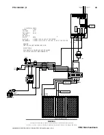
Page 41: ...P DOOR AND FRAME HEATERS BK W BL R LIGHT SWITCH LED DISPLAY FRAME HEATER ELEC TRON 3 S 226 1 2 7 8 3 4 9 10 11 12 23 24 25 26 W BK COMPRESSOR RELAY OUT3 OUT2 OUT1 OUT4 RS 485 MODULE RTN400 SM OUT2 OUT3 OUT1 OUT4 LINE 1 2 3 4 5 6 7 8 9 10 11 12 13 14 18 19 20 21 22 23 24 25 26 27 28 29 30 31 32 33 GND D GND D OC 12V TTL OPTIONAL SENSOR TEMP DEFROST ORANGE 12V D GND KEYB 15 cm MAX NEUTRO NEUTRO NO P...

Page 42: ...42 Technical Data P N 3034041_D U S Canada 1 800 922 1919 Mexico 1 800 890 2900 www hussmann com BL R POWER SUPPLY LINE BK W END LED FUSE 0 6 A NEUTRO LINE2 VRM1B E ...

Page 43: ...Y 60 HZ W WHITE BK BLACK R RED BL BLUE BW BROWN WARNING UNPLUG THE UNIT BEFORE SERVICING ADVERTENCIA DESCONECTE EL EQUIPO ANTES DE REALIZAR CUALQUIER SERVICIO O MANTENIMIENTO COMPRESSOR RELAY LH FAN COND COMPRESSOR LH CURRENT RELAY S R C 1 2 1 2 3 NO 2 1 2b 1b GRN GRN PB1 PB2 SENSOR TEMP AIR C E N T E R L E D DOORS AND FRAME HEATERS C E N T E R L E D INPUT OUTPUT LED W BK BK BK W BK RELAY 2 NOTE 3...

Page 44: ...a 1 800 922 1919 Mexico 1 800 890 2900 www hussmann com BL R POWER SUPPLY LINE 1 NEUTRO LINE2 BK W CENTER LED CENTER LED FUSE 1 0 A FUSE 1 0 A BL R POWER SUPPLY LINE 1 NEUTRO LINE2 BK W CENTER LED END LED FUSE 1 0 A FUSE 0 6 A VRM3B VRM2B H H ...

Page 45: ... information or other support contact your Hussmann representative Please include the model and serial number of the product Hussmann Corporation Corporate Headquarters Bridgeton Missouri U S A 63044 2483 01 October 2012 ...

Page 46: ...46 Technical Data P N 3034041_D U S Canada 1 800 922 1919 Mexico 1 800 890 2900 www hussmann com Hussmann Corporation 12999 St Charles Rock Road Bridgeton MO 63044 2483 www hussmann com ...

Reviews: