background image

Operation Manual of Horizontal Lath

19

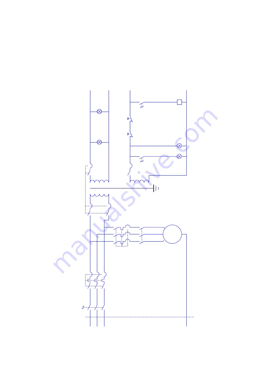
ELECTRIC  CIRCUIT  CONTROL(1/2)

13

L1

L2

L3

PE

U

V W

U

1

V

1

W

1

U

3

V

3W

3

M

4

PU

M

P

Q

M

1

Q

M

2

Q

M

3

Q

M

4

TC

SA

0

H

L

EL

K

A

1

SB

1

K

A

1

24

B

24

A

22

0A

22

0B

D

O

O

R

-F

A

N

22

0V

1U

1W

24

V

M

W

IR

IN

G

  D

IA

G

R

A

M

M

2-

FA

N

M

1

M

3

S

B0

2

1

3

SB

3

S

B0

1

24

C

2

Summary of Contents for HU 410 x 800 VAC TOPLINE

Page 1: ...INSTRUCTION MANUAL MODEL HU410 800VAC TOPLINE...

Page 2: ...e Lathe and Hoisting 12 3 2 Handling 12 3 3 Unpacking 12 3 4 Hoisting 12 3 5 Rules of Safe Hoisting 13 3 6 Installation 14 3 7 Foundation 14 3 8 Position the Lathe by Adjustment Iron Pad 14 3 9 Fix th...

Page 3: ...m Spindle head joining style D5 Spindle reducing bush taper MT6 MT3 Spindle speed grade 2 Spindle speed range 50 2500 rpm Cutting Thread Feed Range and Kind Large screw size 24 mm 6 mm Metric thread r...

Page 4: ...llfully operate the machine The lathe should be operated under the environmental temperature of 5 C 40 C the elevation up to 1000 m the relative humidity of 50 when ambient temperature is 40 C or high...

Page 5: ...peration When operating the lathe you should fully understand the danger of following operations 1 Cutting Fluid The cutting fluid is hazardous to human body To contact the cutting fluid continuously...

Page 6: ...1 3 General Safe Rules for Operator of the Lathe 1 When jigging the workpiece it cannot have oil or grease All parts should be jigged firmly Do not intend to jig the workpiece which is unsuitable or h...

Page 7: ...ot to push the handle to operate the clutch or to witch on power supply to cause accident 21 Master every function and all kinds of operation methods 22 Never put your hands on the chuck or the workpi...

Page 8: ...the workpiece to tighten parts on the lathe Never leap over or go around the chuck or the workpiece to remove iron chips 39 Master suitable method to load and never apply force from unsuitable positio...

Page 9: ...iameter of the chuck 2 When the face chuck is used the chuck guard should be removed If it is indeed required by customer the special chuck guard can be provided but it should be confirmed that only t...

Page 10: ...d sizes and surface roughness can be achieved well If technological rule defines that the workpiece should be ground by emery cloth then the emery cloth should be used in following cases a Nail the em...

Page 11: ...ll be used as it cannot be wound When polish by the emery cloth is made never operate by wearing gloves 2 Level of Noise According to GB T16769 1997 Measurement Method of Sound Pressure Level of Metal...

Page 12: ...if they are robust and reliable in case they are used Do not wind the hoisting tool around the bed as it can cause curvature and damage of the leading screw and the smooth bar 3 2 Handling When handli...

Page 13: ...Operation Manual of Horizontal Lath 13...

Page 14: ...o put the protect sleeve on the hoisting tool to prevent its damage caused by sharp object Each set of the hoisting tool should have clear mark of safe working load with the safe coefficient of 6 1 Fo...

Page 15: ...eration at high speed Suggested time of speed of commissioning Run for 1 hour at 15 of the highest speed Run for 30 min at 30 of the highest speed Run for 30 min at 80 of the highest speed 3 12 Cleani...

Page 16: ...Operation Manual of Horizontal Lath 16 Foundation Drawing...

Page 17: ...Operation Manual of Horizontal Lath 17 4 Power Supply and Connection Input Voltage...

Page 18: ...of 220 V 60 Hz is also available Power supply introduced to each lathe should run through an external distribution cabinet equipped with independent fuse from which wires shall be led into the electri...

Page 19: ...2 13 L 1 L 2 L 3 P E U V W U 1 V 1 W 1 U 3 V 3 W 3 M 4 P U M P Q M 1 Q M 2 Q M 3 Q M 4 T C S A 0 H L E L K A 1 S B 1 K A 1 2 4 B 2 4 A 2 2 0 A 2 2 0 B D O O R F A N 2 2 0 V 1 U 1 W 2 4 V M W I R I N G...

Page 20: ...Operation Manual of Horizontal Lath 20...

Page 21: ...ER IN X POSITION A1 P DISPLAY 220A 220B PE 5V A B C 5G Y POSITION 5V A B C 5G Z POSITION 5V A B C 5G 3 5 5 5 P X Y Z POWER IN A4 V DISPLAY SQ3 12V 12S 24A 24B PE 3 12G 4 4 POWER IN U1 V1 W1 PE TO MOTO...

Page 22: ...Safe Operation of the Lathe Safe Regulations of the Lathe Before starting the lathe read the operation instruction on the manual carefully For the sake of safety please read the guidance of safe oper...

Page 23: ...Operation Manual of Horizontal Lath 23 7 Operation System...

Page 24: ...e Speed 2 Pitch Extension Handle 3 Left Right Screw Handles 4 Tail Sleeve Lock Handle 5 Tail Fast Lock Handle 6 Tail Hand Wheel 7 Feed Handle 8 Apron Longitudinal Hand Wheel 9 Lateral Hand Wheel 10 Sm...

Page 25: ...dle system is not allowed to change speed in motion 7 3 Operation of the Carriage Apron The apron handle is pushed to the front of the limit position lift the black bakelite handle and counterclockwis...

Page 26: ...Operation Manual of Horizontal Lath 26 8 Thread and Feed Table...

Page 27: ...Operation Manual of Horizontal Lath 27...

Page 28: ...Operation Manual of Horizontal Lath 28...

Page 29: ...Operation Manual of Horizontal Lath 29...

Page 30: ...ing oil is not right 2 Lubrication oil is not suitable much or less 3 Clearance of the spindle bearing is too small 1 Fill suitable lubricating oil in the spindle bearings 2 Replace with lubricating o...

Reviews: