8
4.
Initial Cleaning
Machine is shipped with a rustproof oil coating.
Clean the rustproof oil coating from all
exposed metal surface. Then apply oil/grease.
4.2. Minimum Requirement for Housing the Machine
Please comply with the following terms to maximize the life and performance of the machine and its
components.
The Main voltage and frequency complying with the req
uirements for the machine’s motor.
Environment temperature from
–10°C to +50°C.
Relative humidity not over 90%.
Altitude not over 1000m
4.3. Anchoring the Machine
1.
Position the machine on a firm and level
concrete floor.
2.
Maintain a minimum distance of 800mm from
the wall to rear of the machine.
3.
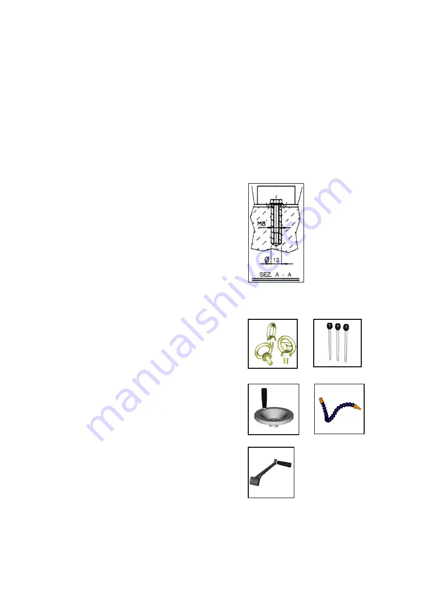
Anchor the machine to the ground, as shown in
the diagram, using screws and expansion
plugs or sunken tie rods that connect through
holes in the base.
4.
Ensure that it is sitting level.
4.4. Assembling Loose Parts
A.
Apply coolant tank cover to tank.
B.
Add the hand wheels to the cross table.
Secure in place by tighten the set screw with
an allen wrench.
C.
Add the quill feed levers to the quill feed shaft
head and tighten down with a wrench.
D.
Add Riser handle to the shaft. Secure in place
by tighten the set screw with an allen wrench.
E.
Attach the coolant nozzle, if you purchase the
optional coolant system.
Hand wheel
Riser handle
Coolant nozzle
Ring bolts
Quill feed
levers
Summary of Contents for HU 45 DM
Page 1: ...HU 45 DM Vario Operation manual ...
Page 19: ...17 9 Drawing and Parts Lists 9 1 Explosion Drawing A Head Motor Electric Control ...
Page 22: ...20 9 4 Explosion Drawing B Head Spindle Assembly ...
Page 24: ...22 9 6 Explosion Drawing C Column Table Base ...
Page 26: ...24 9 8 STAND Explosion Drawing Parts List ...
Page 27: ...25 9 9 Coolant System Explosion Drawing Parts List ...
Page 30: ...28 10 3 Electrical Drawing Wiring Diagram for MD 930 1 ...


