5
2. Transporting the Machine
When transporting in its original own packaging, please
use a forklift truck or hand trolley. Find the proper
position to place machine then anchor it.
3. Getting to Know Your Machine
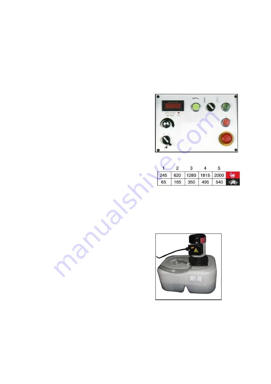
3.1. Control Panel
A. ON Switch
– Starts the motor.
B. OFF Switch
– Stops the motor. As the power still
exists, pressing ON restarts the machine.
C. Emergency Stop Switch
– Stops the machine.
Turn the switch clockwise to unlock the switch
before starting the machine.
D. Forward/Reverse Selector
– Selects the spindle
rotation for tool cutting direction or tapping.
E. Tachometer (optional)
– Displays the rate of
spindle rotation in RPM.
F. Spindle Speed Control Knob
– Changes the rate
spindle rotation.
G. Pump Switch
– Starts the coolant flow for cutting.
H. Drilling/Tapping Selector
– Selects the mode of
operation.
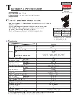
3.2. The Coolant Tank and Pump
The coolant tank holds coolant which pumped to the
work piece for cooling and lubricating while cutting.
Before the operation of a new machine, add coolant to
the coolant tank. When iron filings clog the screen,
cleaning will be required. Before cleaning, uncover the
lid and drain out the coolant.
A
E
D
H
C
B
F
G
Fig. 1
*Speed chart for machines without a
digital display
Summary of Contents for HU 45 DM
Page 1: ...HU 45 DM Vario Operation manual ...
Page 19: ...17 9 Drawing and Parts Lists 9 1 Explosion Drawing A Head Motor Electric Control ...
Page 22: ...20 9 4 Explosion Drawing B Head Spindle Assembly ...
Page 24: ...22 9 6 Explosion Drawing C Column Table Base ...
Page 26: ...24 9 8 STAND Explosion Drawing Parts List ...
Page 27: ...25 9 9 Coolant System Explosion Drawing Parts List ...
Page 30: ...28 10 3 Electrical Drawing Wiring Diagram for MD 930 1 ...


