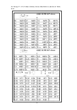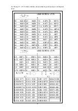
4-7
Gear Box Operation
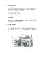
1. Threading
With our special design, there is no need to re-arrange the back gears for
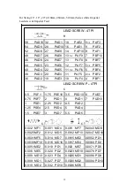
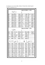
threading. Please refer to the threading and feed tables for correct settings. The
levers used for setting the feed rate or T.P.I are:
a.
Feed direction
○
4
of item 1-1.
b.
Thread/Feed lever
○
5
of item 1-1.
c.
Thread/Feed lever
○
6
of item 1-1
d.
10 step selection dial
○
7
of item 1-1
2. Auto feed
After selecting the proper setting for either feed rate or threading you can use the
appropriate lever for the desired operation. Auto feed
○
16
of item 1-1, or half
nut engagement lever
○
18
of item 1-1.
4-8
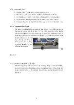
Manual Operation
For manual operation, move both the half nut lever
○
18
and lever
○
4
of item 1-
1 to neutral position. Hand wheel
○
13
Fig. 4-8 controls the apron movement,
○
14
controls the cross slide and
○
32
controls the compound. The graduations on
all the dials are graduated in both metric and inch. Metric is 0.02mm per
graduation and inch is 0.001” per graduation.
Fig. 4-8
14
Summary of Contents for HU 480 X 2200 VAC TOPLINE
Page 1: ...L A T H E MODEL HU 480 X 2200 VAC TOPLINE...
Page 5: ...1 INVERTER TRANSMISSION LATHE 1 1 Machine Assembly 4...
Page 33: ...7 4 Lubrication Location A Oil input hole B Oil drain hole 32...
Page 37: ......
Page 40: ......
Page 41: ......
Page 42: ......
Page 43: ......
Page 44: ......
Page 45: ......
Page 46: ......
Page 47: ......
Page 48: ......
Page 75: ...HU 480 x 2200 VAC TOPLINE...
Page 76: ......


