- 6 -
When the rated control power supply voltage of the shunt trip is DC 24 V, the
maximum length of the copper conductor shall meet the requirements of
Table 7.
Table 7 Maximum length of the copper conductor
Conductor area
Rated control
power supply voltage
Uc (DC 24 V)
1.5mm
2
2.5mm
2
100% Uc
150m
250m
80% Uc
100m
160m
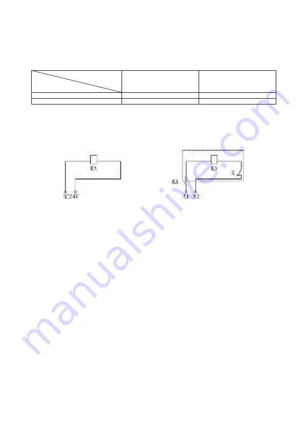
If the requirements of the above table are not met, it is recommended to
design the control circuit of the shunt trip according to Figure 1.
Inside the dotted line box is the
schematic diagram of the shunt
trip
Power supply input
KA: DC24V. The current
capacity of the
intermediate relay
contact is 1 A.
The voltage of the input terminal of the
power supply is: AC 50 Hz 230 V, 400 V
Figure 1 Shunt trip control circuit design
6.4 Parameters of the undervoltage release
Rated voltage Ue: AC: 110 V, 230 V, 400 V;
DC: 24 V, 48 V, 110 V.
The circuit breaker can interrupt reliably under (35%~70%) Us, and the
operating time is 10 ms~30 ms. When the power supply voltage is less than
35% Ue, the circuit breaker can be prevented from closing. When the power
supply voltage is more than or equal to 85%, the circuit breaker can be
reliably closed.
6.5 Special release with prepaid kilowatt-hour meter
The rated working voltage Ue of the special release with prepaid kilowatt-
hour meter is AC 240 V/50 Hz. It can work normally in the range of
(65%~110%) Ue. When the Ctrl terminal is cut off, the breaker will delay
opening by 0.5 s ~ 2 s. See Figure 2 for the wiring diagram.


