HUW1
Series Intelligent Universal Circuit Breaker
29
8
Dual Power Controller
8.1
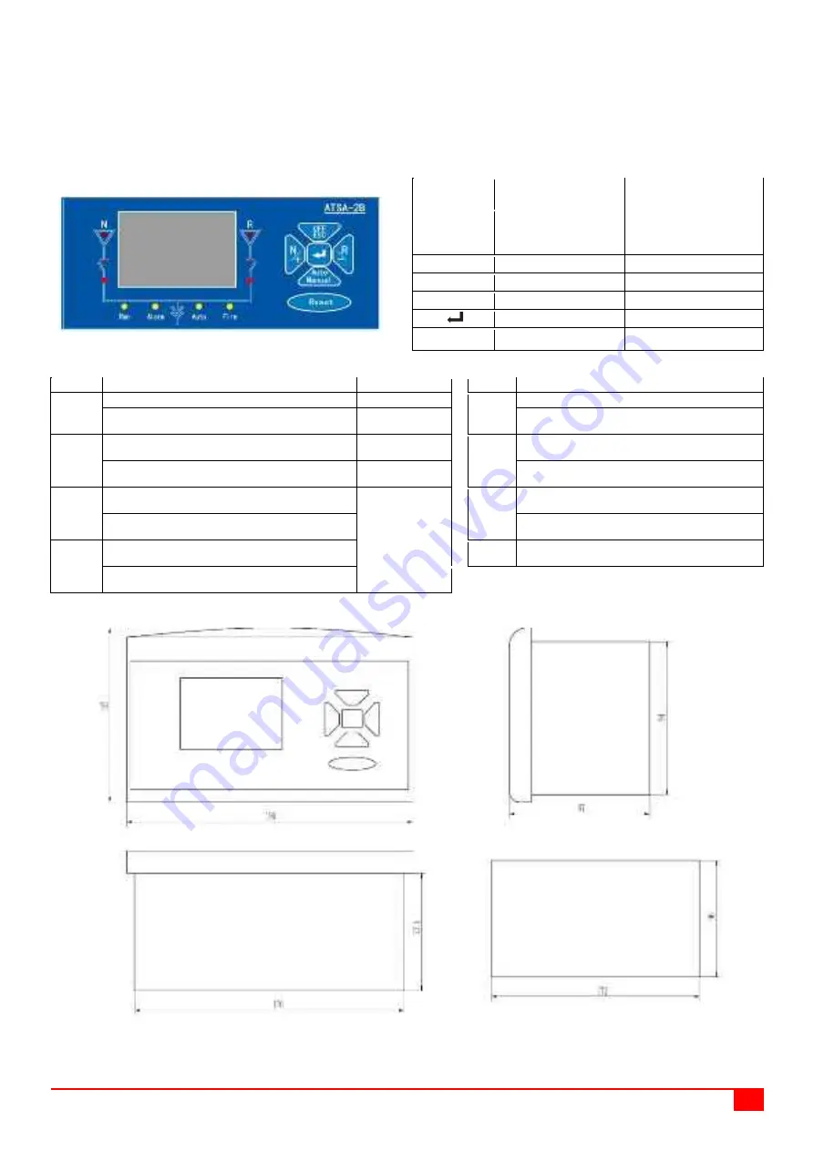
Operation interface and symbol meaning of the dual power controller
Dual power controller interface
Key description
Name of key
Manual operation
mode
Automatic operation
mode
Auto/Manual
Selection key of
manual operation
mode
Selection key of
automatic operation
mode
OFF/ESC
Disconnection
Escape key
N/+
Common
+ (Up) key
R/-
Standby
- (Down) key
Confirm (select) key
Reset
Controller reset
Controller reset
Indicator light description
Indicator light description
Name
Definition
Notes
Name
Definition
N (up)
ON: The common voltage is abnormal
Run
Flash: The controller is running
OFF: The common voltage is normal
Normally On or Off: The controller is in a fault
state
R (up)
ON: The standby voltage is abnormal
Alarm
ON: The dual power supply has alarm
information
OFF: The standby voltage is normal
OFF: The dual power supply has no alarm
information
N
(down)
ON: The dual power switch is in the common
power supply position
N
&
R OFF:
The dual power
switch is in the
off position
Auto
ON: The dual power switch works in
automatic operation mode
OFF: The dual power switch is not in the
common power supply position
OFF: The dual power switch works in manual
operation mode
R
(down)
ON: The dual power switch is in the standby
power supply position
Fire
Fire control signal indicator light
OFF: The dual power switch is not in the
standby power supply position
8.2
Outline and installation dimensions of the dual power controller
Note: When installing, put the dual power controller into the opening of the panel, and clamp the controller on the panel with four
clips.
Important reminder: To ensure the normal operation of dual power supply products and prevent operation errors, the dual power
controller products need to be equipped with corresponding mechanical interlock devices.
Panel opening dimension


