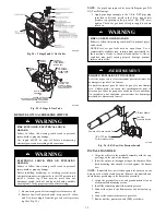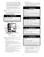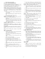
21
7. Turn on furnace power supply.
GAS INPUT RATE INFORMATION
See furnace rating plate for input rate. The input rate for natural
gas is determined by manifold pressure and orifice size.
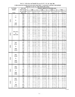
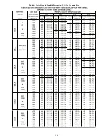
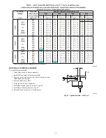
Determine natural gas orifice size and manifold pressures for
correct input at installed altitude by using Table 5 or 6.
NOTE
: All models in all positions except Low NOx models in
downflow and horizontal positions use Table 5 (22,000 Btuh per
burner). Low NOx models in downflow or horizontal positions
must use Table 6 (21,000 Btuh per burner). See input listed on
rating plate.
1. Obtain yearly heat--value average (at installed altitude) for
local gas supply.
2. Obtain yearly specific--gravity average for local gas sup-
ply.
3. Find installation altitude in Table 5 or 6.
NOTE
: For Canada altitudes of 2000 to 4500 ft., use U.S.A.
Altitudes of 2001 to 3000 ft. In Table 5 or 6.
4. Find closest natural gas heat value and specific gravity in
Table 5 or 6.
5. Follow heat--value line and specific--gravity line to point
of intersection to find orifice size and high-- and low--heat
manifold pressure settings.
Furnace gas input rate on rating plate is for installations at
altitudes up to 2000 ft. (610 M).
In the U.S.A
.; the input rating for altitudes above 2000 ft.
(610M) must be reduced by 4 percent for each 1000 ft. (305 M)
above sea level.
In Canada
; the input rating must be derated by 5 percent for
altitudes of 2000 ft. (610 M) to 4500 ft. (1372 M) above sea
level.
The Conversion Kit Rating Plate accounts for high altitude
derate.
SET GAS INPUT RATE
1. Make sure the gas supply is turned off to the furnace and
at the electric switch on the gas valve.
2. Remove the 1/8--in. NPT plug from the outlet pressure tap
on the gas valve.
3. Connect a manometer to the outlet pressure tap on gas
valve.
4. Turn on furnace power supply.
5. Turn gas supply manual shutoff valve to ON position.
6. Turn furnace gas valve switch to ON position.
7. Verify SW1-2 (LHT) on furnace control is turned “ON”.
8. Jumper R and W/W1 thermostat connections to call for
heat.
9. Check manifold orifices for gas leaks when main burners
ignite.
10. Adjust gas manifold pressure. Refer to Table 5 or 6.
11. Remove caps that conceal adjustment screws for gas valve
regulators.
12. Adjust low--heat input rate manifold pressure for natural
gas.
13. Turn low--heat adjusting screw counterclockwise (out) to
decrease input rate or clockwise (in) to increase input rate.
NOTE
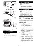
: When correct input is obtained, main burner flame
should be clear blue, almost transparent (See Fig. 12).
14. Jumper R, W/W1 and W2 on control center thermostat
connections. This keeps furnace locked in high--heat oper-
ation.
15. Adjust high--heat input rate manifold pressure for natural
gas.
16. Turn high--heat adjusting screw counterclockwise (out) to
decrease input rate or clockwise (in) to increase input rate.
17. Replace caps that conceal gas valve regulator adjustment
screws.
NOTE
: When correct input is obtained, main burner flame
should be clear blue, almost transparent (See Fig. 12).
18. Remove jumper across R, W1, and W2 after high--heat ad-
justment to terminate call for heat.
19. Turn setup switch SW1-2 (LHT) on furnace control to
OFF position.
20. Turn furnace gas valve switch to OFF position.
21. Turn off furnace power supply.
22. Remove manometer and re-install manifold pressure tap
plug.
23. Turn furnace gas valve switch to ON position.
24. Turn on furnace power supply.
25. Set room thermostat to call for heat.
26. Check pressure tap plug for gas leaks when main burners
ignite.
27. Check for correct burner flame.
28. After making the required manifold pressure adjustments,
check and adjust the furnace temperature rise per the fur-
nace installation instructions.
LABEL APPLICATION
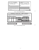
1. Fill in Conversion Responsibility Label 338304--205 and
apply to Blower Access Door of furnace as shown. Date,
name, and address of organization making this conversion
are required. See Fig. 28.
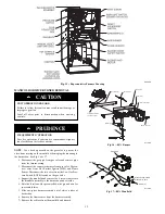
2. Attach Conversion Rating Plate Label 338304--204 to
Outer Door of furnace. See Fig. 29.
3. Apply Gas Control Conversion Label:
a. For 2--stage J and G gas valves, use Gas Control Conver-
sion Label 338304--202. (DO NOT use 338304--203,
which is similar.)
b. For 2--stage E gas valve, use Gas Control Adjustment La-
bel 338304--203. (DO NOT use 338304--202, which is
similar.)
CHECKOUT
1. Observe unit operation through two complete heating
cycles.
2. See Sequence of Operation operation in furnace Installa-
tion, Start--Up, and Operating Instructions.
3. Set room thermostat to desired temperature.

