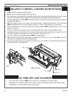
HVFL Unvented Gas Logs
59D1016
15
FP2112
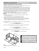
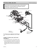
wiring diagram
12/08
Wall
Switch
On/Off Switch
On/Off
Switch
Millivolt
Valve
ODS Pilot
TH = 3
TP = 1
TP/TH =
ODS Pilot
Spade Terminal
Switch
Optional Wall
Switch, Remote
Receiver or
Optional T-Stat
FP11
Figure 18 -
Wiring Diagram
ELECTRICAL WIRING - MILLIVOLT
Label all wires prior to disconnection when servicing controls.
Wiring errors can cause improper and dangerous operation.
Verify proper operation after servicing.
W
ARNING
The milli-volt valve is a self-powered combination gas
control
THAT DOES NOT REQUIRE 110 VAC TO OPER-
ATE.
CONNECT OPTIONAL WALL SWITCH OR
THERMOSTAT
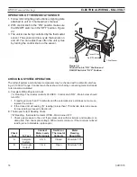
1. Use 18 awg, two-wire cable, 15 feet maximum length.
. At one end of the cable, connect both wires to the wall
switch or thermostat. At the other end, connect one
wire to TP/TH and one wire to TH, or connect the wall
switch/thermostat to the two male (0.5") terminals on
the left side of the unit. The color of the wires does not
matter.


