HVFL Unvented Gas Logs
59D1016
17
ELECTRICAL WIRING - MILLIVOLT
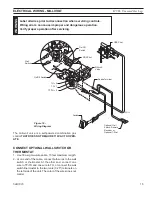
5. Route wiring harnesses through large hole on side of unit. Mount bracket to side of unit with
screw provided.
Figure 22
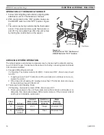
6. Attach wiring harness to either TP/TH and TH on control valve or to existing wiring harness
with two () 0.50" male spade terminals for remote or t-stat option.
Figures 22 and 23.
7. Install knob to shaft of t-stat sensor.
Figure 22.
8. Place thermo bulb in front of the firebox for incoming air.
HIGH
LOW
26D33
17
THERMOST
AT
SETTING
FP2807
Install tstat
Knob
Thermo Bulb
Screw
T-Stat Sensor
and Bracket
Wiring Harnesses
FP807
Figure 22 -
Install T-Stat Sensor to HVFL Base
FP2808
attach tstat to valve
Figure 23 -
Attach Wiring Harnesses to Control Valve
Wiring Harnesses
TH
TP/TH
FP808

