HWg-SMS-GW3 manual
HW group
www.HW-group.com
4
First start
Connecting the cables
Note down the MAC address of the device, printed on the side of the unit.
Set DIP switches to
DIP1=Off, DIP2=Off
.
Connect HWg-SMS-GW to the Ethernet network.
Plug the power adapter and connect it to a connector on the device.
Green
POWER
LED will light up.
If the connection to Ethernet network is working,
LINK
LED will light up (orange light on RJ45
connector) and it then flashes during the data transmission (Activity signalisation).
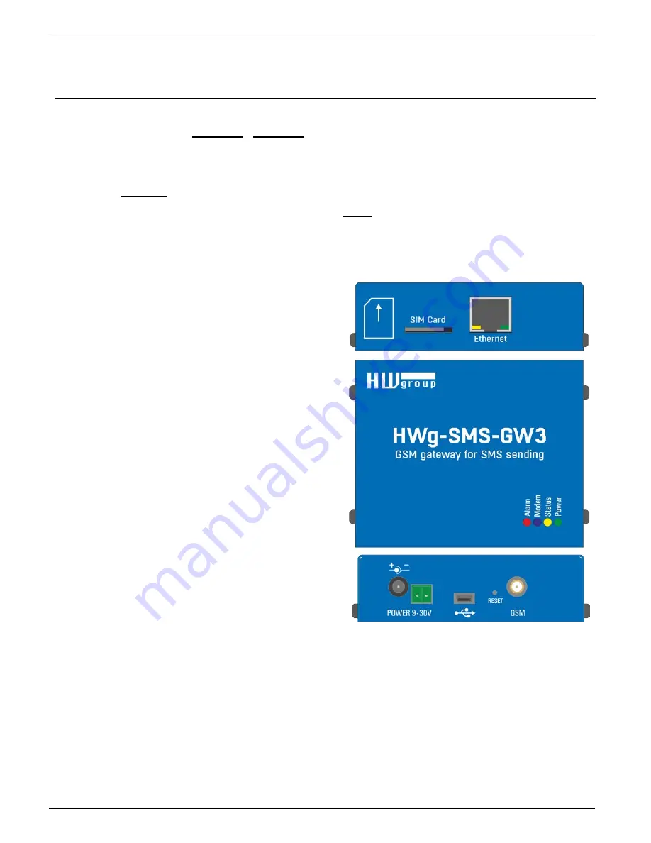
Connectors
Power
Connect the power adapter (9-30V)
USB
A connector for service purposes
Ethernet
Network/data connector
GSM SIM
A SIM card socket.
GSM
An SMA connector for connecting an
external antenna
Reset
Reset button for restoring the factory
default settings – more on page 3
LED indication
•
Power (green)
– Power supply connected
•
Status (yellow)
– Flashes slowly if the device is
working correctly
•
Alarm (red)
– Device /Modemu error. Lights up
if out of signal, flashes in case of SIM card
errors (incorrect PIN entered, etc.)
•
Modem (blue)
– Flashes during SMS sending
•
Link Activity (yellow LED on the Eth. connector)
– Flashes during network activity
•
Link OK (green LED on the Eth. connector)
– Light on when connected to Ethernet


