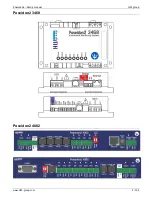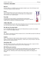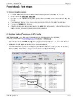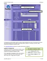
Poseidon2
– Family manual
HW group
www.HW-group.com
6 / 104
Connectors description
Ethernet
Ethernet 100Base-T (10/100Mbit). After connecting the adapter a green "Link" LED shows correct
connection and yellow "Activity" LED flashes
Power
Green LED light shows that the device is powered-up. Power supply in range 9-
30V is required, for Poseidon2 3268 it is 48V. Modules can be manufactured in
PoE versions for use in specific projects
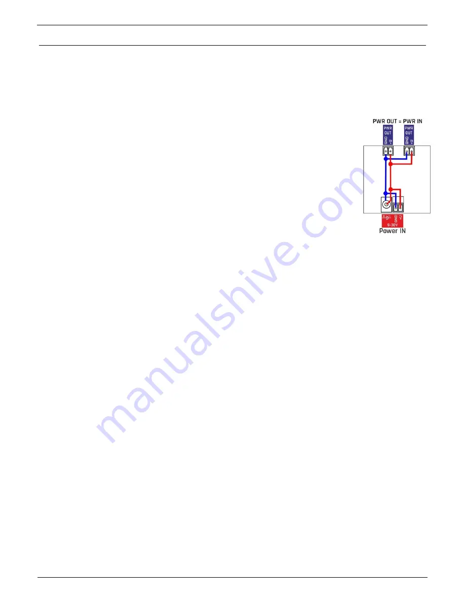
PowerOut
Can be used as a power supply for connected sensors and accessories.
PowerOut output is directly connected to 9-30V input. Power outputs on units that
require 48V can be used as a 12V/300mA power supply.
1-Wire/1-Wire UNI
Connecting HWg sensors with 1-Wire/1-Wire UNI interface. Each port can directly connect up to 60m
bus. 2 Wire UNI sensors. More in chapter
Connecting the sensors
RS-485 (only Poseidon2 4002)
For connecting RS-485 HWg sensors. TermA and TermB switches are used for bus termination.
More in chapter
Connecting the sensors
Inputs
INx - Inputs for connecting dry contacts. All inputs have one common GND potential. Green LED light
shows that the input is triggered.
Outputs
OUTx
– relay outputs with switch contacts. Clamps connected in normal state are NCx (Normally
closed) + COMx (Common), NOx (Normally Open) + COMx when the relay is switched. Yellow LED
light shows that an output is switched.
Alarm/Setup LED
Red LED shows the device state - Light indicates alarm state (some sensors or inputs out of their
safe range), flashing indicates that the device is in TCP or Serial Setup.
DIP1/DIP2 system switches
DIP1 - Serial setup mode activation / Factory default settings switch. Factory default settings can be
restored by switching the DIP1 3x within 5 seconds after connecting the power adapter.
DIP2 - Safe mode - Switching the DIP activates HWg settings protection. No settings can be
changed.


