


Title
Revision.
Page
054 SERIES RELEASE2
R2.Ver2.0
P.20
2-9) Connector (Internal)
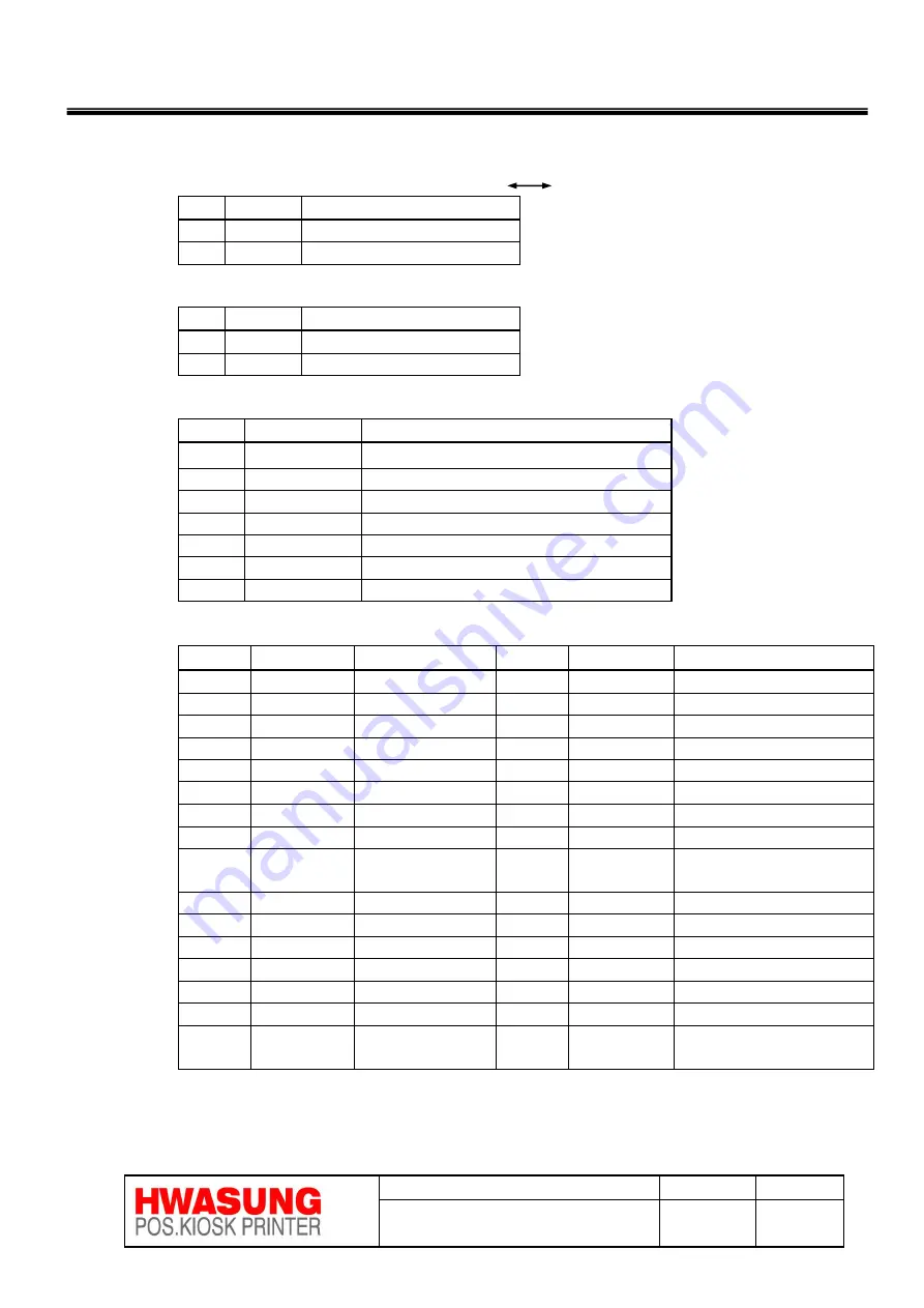
1)CN1 : Power connector (YAW396-02, Yeonho) Housing : YH396-02
Pin
Circuit
Remark
1
V+
+24
2
V-
GND
2)CN2 : Power switch connector (YMW025-02R,Yeonho,or 5268-02A, Molex)
Pin
Circuit
Remark
1
V+
+24
2
V+
+24
3)CN3 : Functional extension connector (20017WS-07P,Yeonho,or 53014-07, Molex )
Pin
Circuit
Remark
1
VCC_A
LED power (680 ohm resistance)
2
VDD
+5V
3
ERR_LED
Erro LED Output
4
FEED_IN
FEED SW Input
5
NEAR_C
Near end sensor Input
6
A
Near end sensor Power
7
GND
4)CN4 : Mechanism connector (SMW200-32C,Yeonho)
Pin No.
Circuit
Remark
Pin No.
Circuit
Remark
1
Vp
+24V
17
/STROBE2
TPH STROBE2
2
Vp
+24V
18
SI
TPH Serial Input
3
Vp
+24V
19
Vp
+12V
4
CLK
TPH CLOCK
20
Vp
+12V
5
/LATCH
TPH LATCH
21
CUT_A
Cutter Control A
6
/STROBE1
TPH STROBE1
22
CUT_B
Cutter Control B
7
TH
Thermister
23
HM_SW
Cutter Home Switch
8
GND
GND
24
Paper_A
Paper sensor power
9
GND
GND
25
Paper_C
Paper sensor output
signal
10
GND
GND
26
HD_UP
Cover open signal
11
GND
GND
27
A
Motor Operation A
12
GND
GND
28
B
Motor Operation B
13
GND
GND
29
/A
Motor Operation /A
14
GND
GND
30
/B
Motor Operation /A
15
VDD
+5V
31
MARK_A
Blackmark sensor power
16
/STROBE3
TPH STROBE3
32
MARK_C
Blackmark sensor output
Signal


