background image

ZX7-315/400/500/630IGBT OPERATOR’S MANUAL

- 3 -

a. Remove fire hazards from the welding area. If this is not possible, cover them to prevent the welding
sparks from starting a fire. Remember that welding sparks and hot materials from welding can easily go
through small cracks and openings to adjacent areas. Avoid welding near hydraulic lines. Have a fire
extinguisher readily available.
b. Where compressed gases are to be used at the job site, special precautions should be used to prevent
hazardous situations.
c. When not welding, make certain no part of the electrode circuit is touching the work or ground.
Accidental contact can cause overheating and create a fire hazard.
d. Do not heat, cut or weld tanks, drums or containers until the proper steps have been taken to insure that
such procedures will not cause flammable or toxic vapors from substances inside. They can cause an
explosion even though they have been “cleaned”.
e. Vent hollow castings or containers before heating, cutting or welding. They may explode.
f. Sparks and spatter are thrown from the welding arc. Wear oil free protective garments such as leather
gloves, heavy shirt, cuffless trousers, high shoes and a cap over your hair. Wear ear plugs when welding
out of position or in confined places. Always wear safety glasses with side shields when in a welding area.
g. Connect the work cable to the work as close to the welding area as practical. Work cables connected to
the building framework or other locations away from the welding area increase the possibility of the
welding current passing through lifting chains, crane cables or other alternate circuits. This can create fire
hazards or overheat lifting chains or cables until they fail.

Summary of Contents for ZX7-315IGBT

Page 1: ...ZX7 315 400 500 630IGBT OPERATOR S MANUAL 1 ZX7 315 400 500 630IGBT INVERTER DC ARC WELDING MACHINE OPERATOR S MANUAL PLEASE READ CAREFELLY BEFORE OPERATING CHENGDU HUAYUAN ELETRIC EQUIPMENT CO LTD ...

Page 2: ...Make certain the insulation is large enough to cover your full area of physical contact with work and ground c Always be sure the work cable makes a good electrical connection with the metal being welded The connection should be as close as possible to the area being welded d Ground the work or metal to be welded to a good electrical earth ground e Maintain the electrode holder work clamp welding ...

Page 3: ...e been taken to insure that such procedures will not cause flammable or toxic vapors from substances inside They can cause an explosion even though they have been cleaned e Vent hollow castings or containers before heating cutting or welding They may explode f Sparks and spatter are thrown from the welding arc Wear oil free protective garments such as leather gloves heavy shirt cuffless trousers h...

Page 4: ...n Usage and Application Range 5 Working Environment 5 Technical Specifications 6 Hardware Overview 7 General Description 7 Delivery and Storage 8 Installation and Adjustment 8 Operation 9 Maintenance 10 Troubleshooting 10 Packing List 11 Wiring Diagrams 12 ...

Page 5: ...ltage fluctuation compensation function keep stable output current High efficiency Low non load loss Small volume light weight easy to move 1 2 Model specification This welding machine designed and produced according to the GB15579 1 2004 JB T7824 1995 Model Z X 7 IGBT Insulated bipolar transistor Rated welding current Invert Slope control Rectified arc welding machine Note if there is a Q in the ...

Page 6: ...7 630IGBT Input power Three phase 380V 15 50 60HZ Rated input capacity KVA 13 8 19 7 26 3 36 2 Rated input current A 21 30 40 55 Open circuit voltage V 74 77 80 Rated welding current A 315 400 500 630 Rated welding voltage V 32 6 36 40 44 Rated duty cycle 60 Current range A 20 315 30 400 40 500 50 630 Weight kg 35 38 42 43 Dimension L W H mm 570 290 530 640 290 530 Rated duty cycle 60 means take 1...

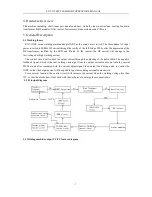
Page 7: ...reactor the HF current will change to the low voltage but high welding current The control circuit will control the output current through the adjusting of the pulse width The negative feedback signal which is the real welding current get from the output current sensor put into the special PWM circuit after compared with the current adjust signal then output the driving pulse to control the IGBT s...

Page 8: ...wire CSA should no less than the following table 7 3 Requirements table Parameter Model CSA for input copper wire mm2 Breaker capacity A Fuse protector A CSA for ground lead cable mm2 ZX7 315IGBT 4 40 20 4 ZX7 400IGBT 4 40 32 4 ZX7 500IGBT 6 60 40 6 ZX7 630IGBT 6 60 50 6 Warning Completely read the operator s manual before installation strictly follow the installation requirements The 3 phase inpu...

Page 9: ...it cooled down if still have problem please contact Huayuan company 8 Operations 8 1 Front panel instruction 1 Digital meter 2 Current voltage select switch 3 Power indicator 4 Overload indicator 5 Lack voltage indicator 6 Hot current adjust knob 7 Arc force current adjust knob 8 Welding current adjust knob 9 Remote local control select switch 10 Remote control connector 8 2 operating instruction ...

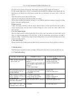
Page 10: ...mplete welding Usually for the average current welding the arc force current can decrease even to zero so that it can reduce spatter 4 Hot current adjust When use small current welding properly adjust the hot current can increase the arc striking success ratio 9 Maintenance Install and operate the machine strictly according to the operator s manual the warranty period is one year 10 Troubleshootin...

Page 11: ...an 2 Stop welding let the machine operate for 10min without load Machine not work but the lack voltage indicator on The input lack phase or lack voltage Check three phase input Attention Only qualified technicians should perform troubleshooting work on the machine If for any reason you do not understand the test procedures or are unable to perform the tests repairs safely please contact us for tec...

Page 12: ...ZX7 315 400 500 630IGBT OPERATOR S MANUAL 12 ...

Reviews: