background image

MP45.12

29JAN01

MAINTENANCE

with rebuilt parts or can be sent to HWH CORPORATION to
be rebuilt, when the system is out of warranty.                     

UNUSUAL CONDITIONS

approximately one inch below the top of the reservoir when 

Do not move the vehicle while the leveling jacks are still in

OIL LEVEL

ELECTRICAL SYSTEM

The batteries should be in good condition and fully charged.
Weak batteries can cause erratic operation.  Battery cable
terminals and battery posts and connections should be kept
clean.

All electrical connections, especially ground connections,
should be clean, tight, free from corrosion and protected 
from weathering.

OPERATIONAL CHECK

If the red LOW BATTERY indicator light comes on, the 
electrical system should be checked.  If the light comes on, 

can cause erratic operation or damage components.
Contact your dealer or HWH CORPORATION for assistance.

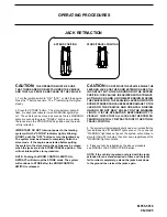
Review the JACK RETRACTION Section.

Make sure the jacks will fully retract to the store position. 
Jacks should not interfere with any part of the vehicle when 
in the store position.

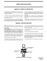
With the jacks extended, check that the jacks can be 
retracted using the "T" handles on the solenoid valves.   
Refer to the MANUAL JACK RETRACTION Section.

contact with the ground.  Retract the jacks according to the
"JACK RETRACTION" Section and then visually check to 
see if the leveling jacks have returned to the 
STORE/TRAVEL position.

It is important that the four leveling jacks and the room are
fully retracted before checking the hydraulic oil level. To 
check the oil supply, remove the breather cap from the top of  
the  hydraulic oil reservoir.  The oil level should be 

NOTE: All major components of the system can be replaced

NOTE:

adequately filled. 

FLUID: HWH Specialty Hydraulic Oil is recommended.  In an

brake fluid or hydraulic jack fluid.  Use of these can damage 

and can cause staining should a leak occur.  DO NOT USE

Dexron automatic transmission fluid contains red dye

emergency Dexron automatic transmission fluid can be used.

seals.

NOTE:

If driving conditions are unusually muddy, the jacks may 

become caked or clogged with mud.  This condition may 
hamper the proper operation of the leveling system.  This 
problem may be prevented or remedied by cleaning off each 
leveling jack if they become excessively muddy.                                                   

In wet or icy weather leveling jacks may become encrusted 

with ice.  This may cause the leveling system to function 

improperly. To eliminate this problem, periodically check the 
leveling jacks and break loose any ice which may be causing

improper operation.

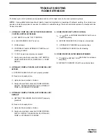
Review the operator manual and run the system in the 

automatic and manual mode. Note any abnormal 
operation.

Check that all lights work according to the INDICATOR 

LIGHT section.  Correct function of the four red WARNING 
lights is essential to the correct operation of the system.

Check that the vehicle is level when all the yellow LEVEL 
indicator lights are out.

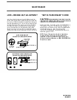
The level sensing unit has an accuracy tolerance of 

+ or - 1 inch side to side, and + or - 5.4 inches front to rear 
on a 36 foot vehicle.

the operation of the system is not interrupted, but low voltage 

Summary of Contents for 610 SERIES

Page 1: ...5 MP05 5209 21MAR01 610 SERIES STRAIGHT ACTING JACKS ROOM EXTENSION SYSTEM HWH COMPUTER CONTROLLED INTERNET http www hwhcorp com CAUTION SECURELY BEFORE REMOVING TIRES OR CRAWLING UNDER VEHICLE UNDERSTAND OPERATOR S MANUAL BEFORE USING BLOCK FRAME AND TIRES SLOPE EXCESS PARK NOT IN TRAVEL HWH COMPUTERIZED LEVELING l LEVEL OFF STORE ON WITH SYNCHRONIZING CYLINDER ON I 80 EXIT 267 SOUTH ...

Page 2: ...ollowing 563 724 3396 OR 800 321 3494 Give your name and coach was purchased or the date of system installation Notify the dealership where you purchased the vehicle or had the leveling system installed Dealership management people are in the best position to resolve the problem quickly If the dealer has difficulty solving the problem he should immediately contact the Customer Service Department a...

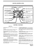
Page 3: ...on CONTROL FUNCTIONS INDICATOR LIGHTS CONTROLS l LEVEL tem is in the store mode OFF BUTTON Push the OFF button to stop hydraulic I BUTTON This is the on button and automatic operation STORE BUTTON The store indicator light is above the UP AND DOWN ARROWS These buttons are for manually LEVELING LIGHTS JACK STORAGE LIGHT This light will flash when the sys JACK DOWN WARNING LIGHTS The four red lights...

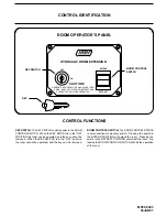
Page 4: ...WITCH When the KEY SWITCH is in the ON POSITION the room can be operated and the key cannot be removed When the KEY SWITCH is in the OFF position the room cannot be operated and the key can be removed The ROOM CONTROL SWITCH is a two position momentary switch Pressing the switch in the EXTEND POSITION will extend the room Pressing the switch in the RETRACT POSITION will retract the room Re leasing...

Page 5: ... should be checked WARNING LIGHTS IT IS THE OPERATOR S RESPONSIBILITY CREATE A DRIVING HAZARD DO NOT RELY SOLELY UPON SEVERE DAMAGE TO THE JACKS AND OR THE VEHICLE AND WITH THE LEVELING JACKS EXTENDED CAN CAUSE WITH STRAIGHT ACTING JACKS MOVING THE VEHICLE OR IN THE EXTEND POSITION THIS VEHICLE IS EQUIPPED LEVELING JACKS ARE STILL IN CONTACT WITH THE GROUND DO NOT MOVE THE VEHICLE WHILE THE CAUTIO...

Page 6: ...ND OBSTRUCTIONS CLEAR OF ROOM WHEN OPERATING extend the room 3 Turn the ignition switch to ACCESSORY 4 Press the I BUTTON if the HYDRAULIC OPERATION LIGHT is not illuminated Refer to the Control Identification page 6 To extend the room press and hold the ROOM CONTROL SWITCH in the EXTEND position until the room is fully extended the operation of the room 7 Press the OFF BUTTON 8 Turn off the ignit...

Page 7: ... released The leveling system will continue to STORE starting from the beginning of the program NOTE NOTE NOTE 3 Insert the KEY and turn the KEY SWITCH to the ON position 5 Turn the KEY SWITCH to the OFF position and remove the KEY IMPORTANT If the leveling system is in the STORE mode do not press the OFF button HWH Customer Service for assistance 1 800 321 3494 room DO NOT reverse direction of th...

Page 8: ...EL position This store for thirty 30 minutes then shut down regardless of the WARNING light does not go out the system will continue to four individual red WARNING lights are out If any one red 3 The system will automatically shut down six minutes after the LEVELING JACKS OR THE ROOM EXTENSION ARE STILL 4 If jacks cannot be retracted by the above procedure IN CONTACT WITH THE GROUND OR IN THE EXTE...

Page 9: ...LVE RELEASE IS OPERATED NOTE if the STORE button on the control panel will not retract the jacks for travel 1 Locate the 4 valve release T handles on the solenoid valves The solenoid valves are located on the pump valve assembly See 2 Allow clearance for vehicle to lower 3 Retract the rear jacks by opening the two outer valves Slowly turn the T handles counter clockwise The handles may turn easily...

Page 10: ...MANUAL RETRACT WINCH IS ENGAGED 7 The system should be repaired before using again WARNING THE MANUAL RETRACT WINCH IS EQUIPPED FOR MANUALLY RETRACTING THE ROOM ONLY IT IS NOT TO BE USED FOR LIFTING OR ANY When manually retracting the room make sure the jacks are retracted before retracting the room OTHER APPLICATION HIGH FORCES ARE CREATED WHEN USING A WINCH CREATING POTENTIAL SAFETY HAZARDS FAIL...

Page 11: ...ully retracted before checking the hydraulic oil level To check the oil supply remove the breather cap from the top of the hydraulic oil reservoir The oil level should be NOTE All major components of the system can be replaced NOTE adequately filled FLUID HWH Specialty Hydraulic Oil is recommended In an brake fluid or hydraulic jack fluid Use of these can damage and can cause staining should a lea...

Page 12: ... confirm that the NOT IN PARK BRAKE indicator light comes on Reset the parking brake The NOT IN PARK BRAKE indicator light should go out Switch the ignition to OFF Level the vehicle by placing a circular bubble level in the center of the freezer floor or location within the vehicle that is to be level With the vehicle level adjust the sensing unit until all yellow lights are off This is done by dr...

Page 13: ...ire electrical connection ROOM CONTROL PUMP or HYDRAULIC CYLINDER 4 ROOM CREEPS OUT AFTER CLOSING A T HANDLE on EXTEND SOLENOID VALVE is not B EXTEND SOLENOID VALVE has an internal leak C HYDRAULIC CYLINDER has an internal leak A T HANDLE on RETRACT SOLENOID VALVE is not closed B RETRACT SOLENOID VALVE has an internal leak ROOM EXTENSION CONTROL SWITCH IS PRESSED properly grounded ROOM CONTROL SWI...

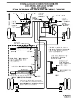
Page 14: ...OTE STEEL TUBE IS USED ON DUAL CYLINDER RAIL ROOM EXTENSIONS ONLY ROD END CAP END ROD END CAP END STEEL TUBE 3 16 HIGH PRESSURE HOSE B 3 16 HIGH PRESSURE HOSE B VIEW 1 DUAL CYLINDER ROOM EXTENSION ROD END 3 16 HIGH PRESSURE HOSE CONNECTION STEEL TUBE HOSE CONNECTION CAP END HOSE CONNECTIONS AT THE REAR OF DUAL CYLINDER ROOM EXTENSION VIEW 1 A A THE LINES B BETWEEN THE ROD END OF THE HYDRAULIC CYLI...

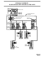
Page 15: ...HECK VALVE INNER CHECK VALVE OUTER SOL VALVE LR SOL VALVE SOL VALVE SOL VALVE RF RR LF PRESSURE RETURN SHUTTLE VALVE 3000 PSI SWITCH JACK PRESSURE SWITCH JACK CYLINDER LEFT REAR RIGHT REAR RIGHT FRONT LEFT FRONT HYDRAULIC SCHEMATIC BI AXIS LEVELING WITH STRAIGHT ACTING JACKS MP65 4525 15MAY97 ...

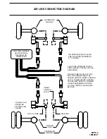
Page 16: ...R DUMP VALVE IS TO TEE INTO THE LINE BETWEEN THE AIR BAG AND THE HEIGHT CONTROL VALVE THREE HEIGHT CONTROL VALVES ARE THE MOST COMMON ON AIR SUSPENSION SYSTEMS 2 3 OR 4 CONTROL VALVES MAY BE USED USE ONLY DOT APPROVED FITTINGS AND TUBING HEIGHT CONTROL VALVE AIR DUMP SOLENOID VALVES ARE ACTIVATED OPENED BY A 12 SIGNAL SEE ELECTRICAL DIAGRAM FOR CONNECTION FROM WIRE HARNESS B A A B A B A B ...

Page 17: ...OWER WIRE BLACK 6800 MASTER RELAY PARK BLUE 9000 ACC FUSE ROOM EXTENSION CONTROL BOX 12 FROM ACC POWER HARNESS 6120 PART SERIAL NO RED GREEN BLACK YELLOW WHITE SENSING UNIT INPUT TOUCH PANEL CABLE INPUT LEVELING SYSTEM CONTROL BOX LR PURPLE 4200 RR BROWN 3200 RF ORANGE 2200 LF BLUE 1200 RED 8500 PRESSURE SWITCH INPUTS LR GREEN 4000 RR BLACK 3000 RF RED 2000 LF YELLOW 1000 GND WHITE 6235 WARNING SW...

Page 18: ... CONNECTIONS BEFORE A B 3000 BLACK RR 6235 SWITCH HARNESS WARNING PRESSURE NOTE TO BOX 10JUL03 MP85 5003 CONTROL BROWN 7699 CONNECTION DIAGRAM LIGHT BUZZER MASTER WARNING PANEL TOUCH MAKE ALL GROUNDING 2000 RED B A ORANGE 2200 SWITCH PRESSURE RF WHITE 6235 WARNING SWITCH TO PARK BRAKE SWITCH LABELED 9000 TO BRAKE LIGHT ON DASH LABELED 9001 FROM 12 ACC FUSED 15AMP MAX BROWN 6120 BLUE 9000 PRESS SWI...

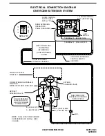
Page 19: ...STEM EXTENSION ROOM CONTROL BOX CONTROL BOX ROOM EXTENSION MANIFOLD ROOM EXTENSION RETRACT SOLENOID VALVE BLACK 5100 EXTEND SOLENOID VALVE YELLOW 5000 HARNESS EXTEND FUSE RETRACT FUSE NOTE THE 4 DIGIT WIRE NUMBER SUPERSEDES ANY AND ALL WIRE COLORS POWER RED 6125 EXTEND YELLOW 7501 RETRACT BLACK 7502 TO ROOM EXTENSION CONTROL SWITCH HARNESS ...

Page 20: ...EE CONTROL BOX CONNECTION INFORMATION SYSTEM ROOM EXTENSION HWH ROOM EXTENSION CONTROL SWITCH ROOM EXTENSION MANIFOLD HARNESS A WHITE 6245 DO NOT REVERSE CONNECTORS WIRE COLORS TO A B ON PACKARD NOTE HARNESS 12 13 11 25 26 24 ROOM EXTENSION PANEL REAR VIEW OPERATOR S KEY SWITCH TERMINAL 13 BLACK 7502 TERMINAL 12 YELLOW 7501 11 13 12 26 25 24 DETAIL A ROOM CONTROL SWITCH SEE DETAIL A 12 11 13 25 24...

Page 21: ...HARNESS GRAY 8600 CABLE TO PUMP FROM HYDRAULIC HARNESS RELAY B STUD RELAY A FROM CABLE 13JAN99 SEE GROUND CONNECTION DIAGRAM CONNECTION DIAGRAM ELECTRICAL CONNECTION DIAGRAM MASTER AND PUMP RELAY FOR 610 SERIES LEVELING SYSTEMS NOTE THE 4 DIGIT WIRE NUMBER SUPERSEDES ANY AND ALL WIRE COLORS BLACK 6800 RED 8500 WHITE 6231 WHITE 6231 GRAY 8600 WHITE 6231 ...

Page 22: ...EW FROM TANK END WHITE 6240 YELLOW 7600 WHITE 6240 YELLOW BLACK 7601 WIRING DIAGRAM MANIFOLD FOR 610 SERIES LEVELING SYSTEMS 28JAN99 B A SEE GROUNDING INSTRUCTIONS CONNECTION DIAGRAM SYSTEM SEE ELECTRICAL ROOM EXTENSION A B B A B A NOTE PRESSURE SWITCH MAY BE MOUNTED IN A DIFFERENT LOCATION ON THE MANIFOLD NOTE THE 4 WIRE NUMBER SUPERSEDES ANY AND ALL WIRE COLORS WHITE 6234 ...

Page 23: ...LD HARNESS GROUP OF WHITE WIRES 6 INCHES FROM END OF LOOM TO BE GROUNDED TO STUD STUD ROOM EXTENSION MANIFOLD HARNESS HARNESS MANIFOLD LEVELING SYSTEM ROOM EXTENSION MANIFOLD HARNESS PUMP MOUNTING GROUNDING INSTRUCTIONS POWER UNIT HARNESS USE GROUNDING AND 3 8 STAR LOCKWASHERS AS SHOWN PUMP MOUNTED REMOTE FROM FRAME IMPORTANT STAR LOCKWASHER MUST BE USED BETWEEN GROUNDING SURFACE AND WIRE TERMINAL...

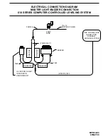
Page 24: ...9 ELECTRICAL CONNECTION DIAGRAM MASTER LIGHT BUZZER CONNECTION LEVELING SYSTEM CONNECTION SEE CONTROL BOX 610 SERIES COMPUTER CONTROLLED LEVELING SYSTEM DIAGRAM NEGATIVE NEGATIVE POSITIVE POSITIVE PURPLE 6111 BROWN 7699 5 AMP FUSE PURPLE IGNITION POWER TO 12 7699 7699 ...

Reviews: