C:\TEMP\ml59101.doc | Revised: 20JUN18 | Page 17 of 39
TROUBLE SHOOTING
PROBLEM
SOLUTION
DIAGRAMS
Step 6b.
Opposing level
lights are on or
a touch panel
level light will
not go out.
Unplug the level sensing unit.
If all touch panel level lights
go out,
the issue is the sensing unit or a short in the harness.
Unplug the main front MIOM connector and make sure no
sensing unit wires are shorted together. If the harness is
good, replace the sensing unit.
If the touch panel level
lights do not go out with the sensing unit unplugged
, the
issue is the harness or the MIOM. Unplug the main front
MIOM connector and make sure no sensing unit wires are
shorted together. If the harness is good, replace the MIOM.
Step 6c. One or
more touch
panel level
lights will not
come on. Some
level lights do
come on.
Unplug the level sensing unit. Ground the four pins that
control the level lights. Make sure only one light comes on
and that it is the correct light.
Pin 1 – wire 0400 – Rear level light
Pin 4 – wire 0100 – Left side level light
Pin 5 – wire 0200 – Front level light
Pin 6 – wire 0300 – Right side level light
If the touch panel lights work properly, replace the sensing
unit. If the lights do not work properly, make sure the harness
wires and connections to the sensing unit and main MIOM
plug are good, fix as necessary. If the wires and connection
are ok, replace the MIOM.
If incorrect touch panel lights come on when grounding pins,
check the wire/pin locations. Most likely a harness is pinned
wrong.
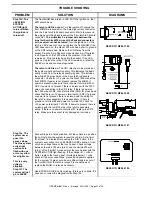
SEE WIRE
LEGEND
BELOW
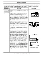
PIN 1 - BLACK - 0400 - SWITCHED GROUND WHEN REAR IS LOW
PIN 2 - WHITE - 6231 - GROUND FROM SENSING UNIT
PIN 3 - RED - 6121 - +12 VOLT FOR SENSING UNIT
PIN 4 - BLACK - 0100 - SWITCHED GROUND WHEN LEFT SIDE IS LOW
PIN 5 - BLACK - 0200 - SWITCHED GROUND WHEN FRONT IS LOW
PIN 6 - BLACK - 0300 - SWITCHED GROUND WHEN RIGHT SIDE IS LOW
SEE
ELECTRICAL
CONNECTION
DIAGRAM
FRONT AIR
MANIFOLD
I/O MODULE
MP84.3180
SEE ELECTRICAL CONNECTION
DIAGRAM - HARNESS ROUTING
MOUNTING / ADJUSTMENT
SCREWS (3)
A
B
D
C
YELLOW LEDS
BOTTOM VIEW OF
SENSING UNIT
LED A - FRONT OF VEHICLE
LED B - LEFT SIDE OF VEHICLE (DRIVER SIDE)
LED C - REAR OF VEHICLE
LED D - RIGHT SIDE OF VEHICLE (PASSENGER SIDE)
WIRE LEGEND
1 2 3
6
5
4
REFER TO MP84.3433
Step 7. PARK BRAKE CHECK –
If the park brake is not set, the touch panel “NOT IN PARK/BRAKE” light will come on
when pushing a manual UP or DOWN arrow button or the “AIR” button. The light will go out when the button is released
and the system will not perform the function for that button. The “NOT IN PARK/BRAKE” light will also come on if the
“RAISE” or “DUMP” buttons are pushed. These two functions will work without the park brake set.
IMPORTANT: Chock the wheels for the following tests and diagnostics.
Make sure the park brake is set and the ignition is in the “ON” or “ACC” position. Push any UP or DOWN arrow button. If
the “NOT IN PARK/BRAKE” light comes on, proceed to Step 7a. If the light does not come on, set the foot brake, release
the park brake and push any UP arrow button. The “NOT IN PARK/BRAKE” light should come on. Set the park brake and
push any UP arrow button. The “NOT IN PARK/BRAKE” light should not come on and the system should function.
Step 7a. The
NOT IN PARK
light comes on
with the park
brake set while
pushing an UP
arrow button.
With the park brake set, there should be a ground on the
black 9000 wire on pin D8 of the main MIOM plug.
If there is no ground on the wire
, the issue is the black
9000 wire or its connection to the vehicle park brake switch.
Repair the wire as necessary or consult the vehicle
manufacturer for assistance with the park brake switch.
If there is a ground on the wire,
make sure the wire is
properly seated in the plug. If the wire is ok, replace the
MIOM.
Step 7b. The
NOT IN PARK
light will not
come on while
pushing an UP
arrow button
with the park
brake released.
With the park brake released, there should not be a ground on
the black 9000 wire on pin D8 of the main MIOM plug.
If there is no ground on the wire,
replace the MIOM.
If there is a ground on the 9000 wire,
there is an issue with
the 9000 wire, it is attached directly to a ground or there is an
issue with the park brake switch. Trace the wire to its source
and repair as necessary. If the wire is attached directly to a
ground source, it must be moved to the park brake switch.
Contact the vehicle manufacturer for assistance.
8
7 6
5 4
3 2
1
A
B
C
D
FRONT VIEW OF I/O MODULE
CONNECTOR
REFER TO MP84.3180
OR MP84.3010

