background image

C:\TEMP\ml59101.doc  |  Revised:  20JUN18  |  Page 20 of 39 

AUTOMATIC DIAGNOSTICS 

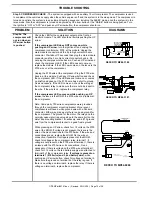
Step 12. For a detailed explanation of the automatic leveling sequence, see “AUTOMATIC OPERATION” in PART 1 
of this manual. 

Make sure the park brake is set. Start the engine and make sure the air tanks are full. Push the “AIR” 

button. The blue SYSTEM ACTIVE light above the “AIR” button should flash. One or two yellow level lights may be on. The 
system will exhaust air from all air bags lowering the vehicle, even if no yellow level lights are lit. If no level lights are on 
after all air has been exhausted from the air bags, the system will go immediately into the SLEEP mode. When all air is 
exhausted from the bags, if any yellow level lights are lit, the system will level the vehicle by raising the low side and/or end 
of the vehicle. When all four level lights are out, the vehicle is level and the processor will go into the SLEEP mode. The 
LEVELING SYSTEM ACTIVE light will now flash rapidly. The ignition key can now be turned off. The LEVELING SYSTEM 
ACTIVE light will continue to flash rapidly.  
 
NOTE: After the initial lowering procedure of automatic leveling, if any yellow level lights are lit, one lower valve and the 
compressor are turned on and will remain on until leveling is achieved or the system goes to EXCESS SLOPE.  
 
EXCESS SLOPE occurs if the system tries to level the vehicle for 15 minutes and a yellow level light remains on.      
 
The SLEEP mode will continue with the LEVELING SYSTEM ACTIVE light flashing rapidly until the “CANCEL” button or 
the “TRAVEL MODE” button is pushed with the ignition in “ON” or “ACC”. Releasing the park brake with the ignition on or 
off will cancel the SLEEP mode and turn the LEVELING SYSTEM ACTIVE light off.  

TROUBLE SHOOTING


PROBLEM 

SOLUTION 

DIAGRAMS 

Step 12a. The 
“NOT IN 
PARK/BRAKE” 
light comes on 
while pushing 
the “AIR” 
button. 

If the system is working with the manual UP and DOWN arrow 
buttons, this is a near impossibility. Review Step 7. 


Step 12b. The 
LEVELING 
SYSTEM 
ACTIVE light 
will not come 
on. 

Push any UP or DOWN arrow button. If the system functions 
with a manual button, replace the touch panel. If the system is 
not functioning in manual, start back with Step 1 and continue 
until the system functions with the manual UP and DOWN  
arrow buttons.  


Step 12c. The 
vehicle is not 
level within  
tolerances after 
auto leveling  

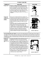
It is critical that the yellow leveling lights and the air bag 
pressure switches are functioning properly. Review Step 6 to 
check the level sensor and Step 8 to check the 20 psi air bag 
pressure switches.  


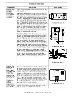
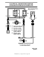
LATCH IN RELAY ASSEMBLY INFORMATION (FOR SLEEP MODE) - 

The ignition can be turned off after automatic 

leveling is complete. The system should remain in the SLEEP mode. There is a relay assembly that is used to latch in 
power to the MIOM and touch panel. This assembly is located within about 18” of the front air module.  
 
The latch in relay assembly will be on any time the ignition is in the “ON” or “ACC” position. There are two relays in the 
assembly labeled CR1 and CR2. Ignition and battery power are routed to the relay assembly. The battery power is routed 
through a reset switch to the normally open contacts of CR1. The reset switch is a momentary, normally close switch and 
should be close to the relay assembly. Main ignition power for the front MIOM and touch panel is routed to the front MIOM 
main connector, pin A1, through this latch in assembly and is used to turn CR1 relay on. The CR1 relay supplies battery 
power to the front MIOM main connector, pin D1, when the ignition is on. 
 
There are four wires between the MIOM and latch assembly: red 6120, +12 ACC power, main connector, pin A1 and red 
6102, +12 battery, main connector, pin D1. The black 7500, sw. +12 for CR2 control and the white 6235, ground for relays 
are in a 2-pin Packard connector at the MIOM. Ground on the 6235 wire is constant. The 6120 +12 ACC wire and the 6102 
+12 battery wire will have +12 volts whenever the ignition is on. The 7500 CR2 relay control wire will have +12 volts 
anytime the ignition is on or with the ignition off if the leveling system is in the SLEEP mode. 


Summary of Contents for 700 Series

Page 1: ...1 3494 or 563 724 3396 Fax 563 724 3408 www hwh com 700 SERIES AIR LEVELING SYSTEM HWH COMPUTER CONTROLLED R R R NOT IN BRAKE PARK TRAVEL MODE CAUTION SECURELY BEFORE REMOVING TIRES OR CRAWLING UNDER VEHICLE UNDERSTAND OPERATOR S MANUAL BEFORE USING BLOCK FRAME AND TIRES DUMP RAISE STOP EMERGENCY TRAVEL MODE SLOPE EXCESS HWH COMPUTERIZED LEVELING LEVEL AIR ...

Page 2: ...ou have encountered The testing and repair for that problem is in the Solution center column Diagrams for a particular Problem and Solution are in the Figurines right hand column This column will direct you to the proper figure in Section 2 Figures for a more detailed view Before beginning your repair it is IMPORTANT to read the CAUTIONS and NOTES AND CHECKS in the first section TROUBLE SHOOTING G...

Page 3: ...ed in order Problems checked for in one step are assumed correct and not checked again in following steps 2 Batteries should be in good condition and fully charged Low voltage can cause erratic operation Important Not all vehicle air suspensions are plumbed the same Consult the vehicle manufacturer for specific plumbing diagrams Also not all vehicles employ the speed switch to latch the DUMP or RA...

Page 4: ...on will lower the whole coach by dumping air from the suspension system RAISE BUTTON This button will raise the whole coach by adding air to the suspension system IMPORTANT Read DUMP AND RAISE FUNCTIONS before using the DUMP and RAISE buttons UP ARROWS RAISE BUTTONS These momentary buttons are used for manually operating the air leveling systems Sides or ends of the vehicle will raise while these ...

Page 5: ...sh slowly if an automatic leveling process is in progress and flash rapidly when in the SLEEP mode When in the SLEEP mode this light will continue to flash rapidly even when the ignition key is off This light will only flash for auto level and the sleep mode and should never be on steady The blue light above the TRAVEL MODE button will flash a few times after the TRAVEL MODE button is pushed It wi...

Page 6: ... then continue with the leveling process as needed Here are a couple examples Scenario 1 The front and left side level lights are on The left side raise loads are on lifting the left side If the front level light flickers the leveling process is not interrupted The left side continues to rise If the left side light flickers the process stops turning the raise loads off until the light comes on sol...

Page 7: ...e side to side first if needed then front to rear The UP and DOWN arrow buttons will not function if the LEVELING SYSTEM ACTIVE light is flashing NOTE There is no EXCESS SLOPE or SLEEP mode in manual leveling If the AIR button is pushed after manually leveling the vehicle even if all yellow level lights are out the auto level sequence will start from the beginning including first dumping all air f...

Page 8: ...e system is functioning properly It is best to check all four sets of UP and DOWN arrows First use the DOWN arrow and check the appropriate bags are empty then push the corresponding UP arrow and make sure the bags have re inflated Each air manifold is equipped with two 20 psi pressure switches one for each side These are normally closed switches The contacts will open at approximately 20 psi Thes...

Page 9: ...ld MIOM These lights should be flashing with the ignition on CHECK THAT ALL LINK LIGHTS ARE FLASHING ALL LINK LIGHTS ARE FLASHING Check for 12 power on the red 6120 wire pin A1 at the front MIOM If 12 power is present replace the MIOM If 12 power is not present there is an issue with the 6120 wire between the front MIOM and the latch in relay assembly Check the wire and plug connections Fix as nec...

Page 10: ... Check for ground on the white 6235 wire at terminal 86 of CR1 and check for 12 on the red 6120 wire at terminal 85 of CR1 If ground is not present check the 6235 wire and its connections to the 2 pin MIOM Packard connector for the latch in assembly Fix as necessary If the wire and connections are good replace the MIOM If 12 power is not present at terminal 85 the issue is with the 6120 wire at th...

Page 11: ...G UNIT SEE MP84 3433 A B FRONT AIR MANIFOLD I O MODULE SEE MP84 3180 SEE MP84 3190 I O MODULE REAR AIR MANIFOLD HWH COMPUTERIZED LEVELING WARNING UNDERSTAND OPERATOR S MANUAL BEFORE USING BLOCK FRAME AND TIRES CANCEL MODE TRAVEL LEVEL MODE TRAVEL RAISE BRAKE PARK SLOPE EXCESS NOTIN DUMP AIR SECURELY BEFORE REMOVING TIRES OR CRAWLING UNDER VEHICLE REFER TO MP84 3060 WARNING DO NOT CRAWL UNDER THE V...

Page 12: ...nition is in the ON or ACC position there should be 12 volts on the black 9900 wire going to the main connector pin C6 of the front MIOM This is the speed switch wire If 12 is not present there is an issue with the transmission output the 9900 wire its connections to the HWH MIOM or the transmission speed switch If 12 is present replace the touch panel NOTE 12 volts will not be present when the ve...

Page 13: ...order is not important Starting with the front then rear then left side and finally the right side would be a good order RIGHT FRONT TRAVEL RIGHT FRONT LOWER RIGHT FRONT RAISE AIR COMPRESSOR LINK LIGHT LEFT FRONT LOWER LEFT FRONT TRAVEL SYSTEM LATCH LEFT FRONT RAISE REFER TO MP84 3180 OR MP84 3190 CONTROL W9700 RELAY COMP W2700 TRAVEL RAISE W2500 W2600 LOWER RS RS RS W7500 RELAY LATCH B A A B A B ...

Page 14: ... to MP44 3500 in the diagram section of this manual for instructions on setting this regulator For the sides or rear of the vehicle or if the front manifold does not have a regulator the issue will be with the vehicle air supply or suspension components All the HWH manifolds can do is let air into the air bags How high the vehicle raises is a function of available air pressure and supply L E F T R...

Page 15: ...and check the compressor LED If the LED does not come on or comes on briefly and goes out the 9700 wire has a short to ground Fix as necessary If the LED comes on check the wiring at the compressor relay to make sure there is not a bad spot in the wire If the wire is ok replace the compressor relay If the compressor LED comes on while pushing an UP arrow the issue is the MIOM the 9700 wire or a pr...

Page 16: ...ND FUSE 15 AMP FLOW GROUND TO RELAY MOUNTING BOLT TO 12 BATTERY POWER 6100 REFER TO MP84 6085 Step 6 YELLOW LEVEL LIGHT CHECK There are 4 yellow leveling lights on the right hand side of the touch panel A lit level light indicates that side or end of the vehicle is low One or two level lights can be on at the same time When all the level lights are out the vehicle should be level Manually level th...

Page 17: ...IGHT SIDE OF VEHICLE PASSENGER SIDE WIRE LEGEND 1 2 3 6 5 4 REFER TO MP84 3433 Step 7 PARK BRAKE CHECK If the park brake is not set the touch panel NOT IN PARK BRAKE light will come on when pushing a manual UP or DOWN arrow button or the AIR button The light will go out when the button is released and the system will not perform the function for that button The NOT IN PARK BRAKE light will also co...

Page 18: ...0A Step 9 TEST FOR 85 PSI SYSTEM PRESSURE SWITCH The 85 psi system pressure switch is on the rear air manifold This is used as a low air pressure warning device only With low system air pressure the ignition on and park brake off the master warning light will be on and the green TRAVEL MODE light will be off It will not interfere with any leveling operation manual or automatic or with the DUMP or ...

Page 19: ...e is ample air supply 110 psi Push the DUMP button to exhaust all air from the air bags Make sure all air bags are totally deflated Push the CANCEL button DO NOT USE THE TRAVEL MODE BUTTON Push the RAISE button The light above the RAISE button should start flashing and all air bags should start to inflate and raise the vehicle Step 11a The light above the RAISE button does not flash Whenever the i...

Page 20: ...view Step 7 Step 12b The LEVELING SYSTEM ACTIVE light will not come on Push any UP or DOWN arrow button If the system functions with a manual button replace the touch panel If the system is not functioning in manual start back with Step 1 and continue until the system functions with the manual UP and DOWN arrow buttons Step 12c The vehicle is not level within tolerances after auto leveling It is c...

Page 21: ...udes the white 6235 ground wire in the 2 pin latch in Packard connector Check for 12 power on the black 7500 wire at the front MIOM If power is not present replace the MIOM If power is present make sure there is power to terminal 85 of CR2 If power is not present there is an issue with the 7500 wire or its connection to the CR2 relay If there is power on the 7500 wire at CR2 check terminal 86 CR2 ...

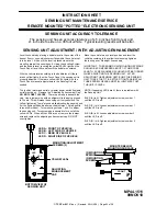
Page 22: ...ENSING UNIT WHILE ADJUSTING THE SENSING UNIT AFTER ADJUSTING THE SENSING UNIT BUMP THE SENSING UNIT TO SEE THAT IT IS SETTLED TIGHT AGAINST ALL THREE SCREW HEADS AND STILL INDICATES THAT THE UNIT IS LEVEL Level the vehicle by placing a bubble level in the center of the freezer floor or upon whichever surface within the vehicle that is to be level It is best if the level is placed close to the moun...

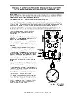
Page 23: ...e at all when the UP ARROW button is pushed 7 Adjust the regulator up 5 psi from 50 psi to 55 psi Remember to support the vehicle before crawling under the 8 Again push and hold the front UP ARROW button until the front of the vehicle stops rising Measure at the trim line again and record the measurement 6 Measure from the ground to the trim line of the vehicle at the approximate center of both fr...

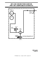
Page 24: ...GRAM HWH AIR COMPRESSOR SEE AIR LINE H C V H C V C V H C V H PRESSURE PROTECTION MANIFOLD TO VEHICLE AIR SUPPLY SEE FRONT AND REAR AIR SOLENOID MANIFOLD CONNECTION DIAGRAMS FOR SPECIFIC VALVE AND AIR MANIFOLD CONNECTION INFORMATION HEIGHT CONTROL VALVE 4 AIR SUPPLY MANIFOLD REAR LINES FROM HEIGHT CONTROL VALVES HEIGHT CONTROL LINES FROM MANIFOLD AIR BAGS VALVES LINES TO ...

Page 25: ...P74 2650 13APR10 RAISE LOWER TRAV RAISE LOWER TRAV EXH EXH AIR LINE CONNECTION DIAGRAM MANIFOLD ASSEMBLY SEE AIR LINE CONNECTION DIAGRAM HWH AIR COMPRESSOR SCHEMATIC EXH HCV EXH HCV LOWER TRAV LOWER RAISE AIR BAG EXH RAISE TRAV EXH AIR BAG NORMALLY CLOSED PRESSURE SWITCH PRESSURE PROTECTION MANIFOLD TO VEHICLE AIR SUPPLY 85 PSI PRESSURE CLOSED NORMALLY SWITCH 20 PSI ...

Page 26: ...ALVES CANNOT FOR AIR PRESSURE SWITCHES AND AS SHOWN GROUND SUPPLY WIRES CONNECTIONS MUST BE MAINTAINED PRESSURE REGULATOR AIR SUPPLY HCV IS USED IMPORTANT SOLENOID VALVE LEFT VALVE NOT SHOWN VALVE NOT SHOWN RIGHT RAISE VALVE 2 CHECK RIGHT TRAVEL SOLENOID VALVE LEFT VALVE NOT SHOWN RIGHT LOWER SOLENOID VALVE LEFT A A B B A B A B PSW RS B A B A B B A A B B A A B B A B A A B B B A A A NASON MODEL SM ...

Page 27: ...T AND RIGHT BE INTERCHANGED AIR SOLENOID VALVES CANNOT FOR AIR PRESSURE SWITCHES AND AS SHOWN GROUND SUPPLY WIRES CONNECTIONS MUST BE MAINTAINED PRESSURE SWITCH 85 PSI AIR SUPPLY HCV IS USED IMPORTANT SOLENOID VALVE LEFT VALVE NOT SHOWN VALVE NOT SHOWN RIGHT RAISE VALVE 2 CHECK RIGHT TRAVEL SOLENOID VALVE LEFT VALVE NOT SHOWN RIGHT LOWER SOLENOID VALVE LEFT A A B B A B A B B A B A B B A A B B A A ...

Page 28: ...R LINE CONNECTION DIAGRAM 12 VOLT RELAY AIR FILTER MP74 4622 BATTERY GROUND FROM 12 FLOW RELIEF VALVE 110 PSI AIR SOLENOID TO HWH AIR 12 CONTROL COMPRESSOR FROM HWH AIR LEVELING MANIFOLDS NORMALLY OPEN HWH AIR COMPRESSOR HARNESS 15 AMP FUSE VALVE CHECK ...

Page 29: ...ON DIAGRAM HWH AIR COMPRESSOR SCHEMATIC COMP PRESSOR MOTOR EXHAUST EXHAUST SOLENOID 1 NORMALLY OPEN RELIEF VALVE 110 P S I AUX 12V COMPRESSOR SOLENOID 1 DUMPS WATER OUT OF FILTER WHEN COMPRESSOR IS OFF PORT TO LEVELING SYSTEM MANIFOLDS HWH WATER TRAP 13APR10 MP74 5351 ...

Page 30: ... RIGHT REAR PRESSURE 6233 B LEFT REAR PRESSURE SWITCH 3210 A SYSTEM PRESSURE SWITCH A B B A 6233 6233 3215 4210 PUMP POWER RELAY CONNECTIONS SEE MP84 3290 6230 6100 HWH COMPUTERIZED LEVELING WARNING UNDERSTAND OPERATOR S MANUAL BEFORE USING BLOCK FRAME AND TIRES SECURELY BEFORE REMOVING TIRES OR CRAWLING UNDER VEHICLE CANCEL MODE TRAVEL LEVEL MODE TRAVEL RAISE BRAKE PARK SLOPE EXCESS NOT IN DUMP A...

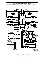
Page 31: ... WHITE D2 6232 SYSTEM GROUND FOR I O MODULES AND TOUCH PANEL D3 NO CONNECTION D4 SW GND FROM LEFT FRONT AIR PRESS SWITCH LOW PRESSURE BLACK D5 1200 SWITCHED GROUND FROM LEVEL SENSING UNIT LEFT SIDE LOW 0100 BLACK D6 SWITCHED GROUND FROM LEVEL SENSING UNIT FRONT LOW BLACK D7 0200 SWITCHED GROUND FROM PARK BRAKE SWITCH PARK BRAKE ON BLACK D8 9000 RIGHT FRONT TRAVEL RIGHT FRONT LOWER RIGHT FRONT RAIS...

Page 32: ... AIR IN VALVE BY PASS B A A B A B B A B A A B A B TRAVEL W1700 LS W1600 LOWER LS LS RAISE W1500 B A B A SEE MP84 6085 SEE MP84 3200 SEE MP84 3290 RED 6100 WHITE 6230 SEE MP84 3180 INFORMATION FOR CONNECTION LEFT FRONT PRESSURE SWITCH RIGHT FRONT PRESSURE SWITCH 6232 6232 1210 2210 1210 2210 6232 RED 6100 WHITE 6234 RED 6100 WHITE 6234 6235 7500 6102 6120 6245 2700 6243 2600 6244 2500 1700 6246 160...

Page 33: ...RES N A C2 N A D1 RED 6122 12 POWER FOR I O MODULE GROUND FOR AIR MANIFOLD PRESSURE SWITCHES WHITE D2 6233 SYSTEM GROUND FOR I O MODULE D3 NO CONNECTION D4 SW GND FROM LEFT REAR AIR PRESS SWITCH LOW PRESSURE BLACK D5 4210 RIGHT REAR TRAVEL RIGHT REAR LOWER RIGHT REAR RAISE LINK LIGHT FRONT VIEW OF I O MODULE CONNECTOR A LIT RED LED INDICATES THERE SHOULD BE 12 VOLTS ON THE CORRESPONDING WIRE LINK ...

Page 34: ...I VALVE BY PASS HCV BAG AXLE AIR IN VALVE BY PASS B A A B A B B A A B A B TRAVEL W4700 LS W4600 LOWER LS LS RAISE W4500 B A B A WHITE BLACK SEE MP84 3190 INFORMATION FOR CONNECTION LEFT REAR PRESSURE SWITCH RIGHT REAR PRESSURE SWITCH 6233 6233 4210 3210 4210 3210 3215 WHITE 6234 RED 6100 A B AIR MODEL SM NASON BAG 6233 3215 6233 6245 3700 6243 3600 6244 3500 TO FRONT I O MODULE HWH MAIN TRUNK HARN...

Page 35: ...FACTURER FOR RELAY MOUNTING LOCATION AND RESET SWITCH LOCATION RESET SWITCH NC 6100 6101 6101 6101 6100 FUSE 5 AMP ACC AND BATTERY CONNECTIONS BY VEHICLE MANUFACTURER ACC TO 12 ACCESSORY TO 12 BATTERY PIN 4 RED 6120 12 ACC TO FRONT I O MODULE HARNESS CONNECTOR HARNESS CONNECTOR TO FRONT I O MODULE PIN 3 RED 6102 12 BATTERY PIN 1 BLACK 7500 SWITCHED 12 FROM FRONT I O MODULE FROM FRONT I O MODULE PI...

Page 36: ...NT SCREWS 3 A B D C YELLOW LEDS BOTTOM VIEW OF SENSING UNIT LED A FRONT OF VEHICLE LED B LEFT SIDE OF VEHICLE DRIVER SIDE LED C REAR OF VEHICLE LED D RIGHT SIDE OF VEHICLE PASSENGER SIDE WIRE LEGEND PIN 1 BLACK 0400 SWITCHED GROUND WHEN REAR IS LOW PIN 2 WHITE 6231 GROUND FROM SENSING UNIT PIN 3 RED 6121 12 VOLT FOR SENSING UNIT PIN 4 BLACK 0100 SWITCHED GROUND WHEN LEFT SIDE IS LOW PIN 5 BLACK 02...

Page 37: ...0 The control box sends a 12 signal to the normally open 12 volt relay The 12 volt relay 2 will energize and the compressor will run The normally open air solenoid 1 will close allowing the compressor to build pressure The normally open air solenoid 1 will open any time the compressor is not running allowing internal pressure moisture to bleed off The check valve 3 will keep the suspension air fro...

Page 38: ...ND RED 12 GROUND WHITE GROUND 12 SIGNAL 15 AMP 12 VOLT BATTERY POWER NORMALLY OPEN 12 VOLT AIR SOLENOID 12 VOLT ESSEX RELAY COMPRESSOR HARNESS FROM FRONT AIR I O MODULE 12 SIGNAL 9700 COMPRESSOR MOTOR FUSE 15 AMP A RELAY MTG BOLT 6100 AIR COMPRESSOR ELECTRICAL CONNECTION DIAGRAM ...

Page 39: ...ISTOR NOTE THERE IS A 120 OHM TERMINATING RESISTOR AT EACH END OF THE TOUCH PANEL HARNESS DO NOT REMOVE CUT OR MODIFY THE HARNESS TOUCH PANEL HARNESS HWH COMPUTERIZED LEVELING WARNING UNDERSTAND OPERATOR S MANUAL BEFORE USING BLOCK FRAME AND TIRES SECURELY BEFORE REMOVING TIRES OR CRAWLING UNDER VEHICLE EMERGENCY STOP MODE TRAVEL LEVEL MODE TRAVEL RAISE BRAKE PARK SLOPE EXCESS NOT IN DUMP AIR PIN ...

Reviews: