After assembly, the boom-to-mast bracket may
be rotated on the boom so that after mounting,
the elements are in an "X" configuration.
Securely tighten the 1/4"-20 x 3/4" hardware.
When the bracket is in the desired position.
ASSEMBLY OF OTHER ELEMENTS
Select the two reflector elements, 3/16" x 39
1/2" (Item 1), marked with 2 black bands near
one end of each. Also select four insulators
(Item 21) and four - 3/16" pushnuts (Item 28).
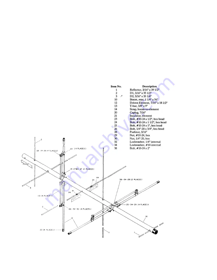
ASSEMBLY OF DRIVEN ELEMENTS
-Select the four (4) driven element halves,
7/16" 'x 18-1/2" (Item 12), T-Bar (Item 13),
boom-toelement strap (Item 14), and driven
element clamps (item 22) and associated
hardware as shown in Figure 2.
Install the reflector elements on the rear boom
as shown in Figure 2. Push one of the element
insulators (Item 21) onto each reflector, so that
its shoulder is 19 1/8" from the nearest end. In-
sert the long end of each reflector into the
reflector mounting holes, as shown in Figure 2.
Assemble the two driven elements to the boom
as shown in Figure 2. The distance from the
boom to the edge of the driven element clamps
(Item 22) should be 8 5/16" (21 cm). Securely
tighten all hardware. When the coax/switch
assemble is installed later, you will decide on
either LHCP or RHCP from the unswitched
polarization.
Figure 2 Assembly of Driven
Elements, Reflectors and
Directors to Boom
Summary of Contents for VB-216SAT
Page 3: ...Figure 1 Boom Assembly ...


