7. Operation Controls and Functions
The following sections describe the hardware components of the unit, along
with how to install and use the device.
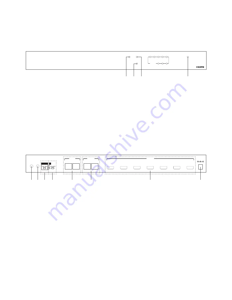
7.1 Front Panel
①
HDMI/DVI indicators: When the LED turns on this means the input source
is HDMI and when the input source is DVI the LED will not turn on.
②
HDCP indicators: When the input source has HDCP protection the
HDCP LED will turn on.
③
SYNC Indicator: The LED will turn on when the input source's signal is
detected by the device.
④
Power LED: The LED will turn on when power is on.
7.2 Rear Panel
①
IR IN: This slot is to be connected with the IR receiver cable included in the
package and use the source’s remote to control source equipment.
②
OUT: This slot connects with the IR blaster cable included in the
package and should be placed it in front of the source for sending and
infrared signal.
③
EDID Control Switcher: Switch the EDID between STD & TV. Switch to STD
to use the built-in EDID or switch to TV to use TV’s EDID. Default factory
setting is on TV, leave as is when the display is working properly.
Note:
1. When EDID is switched to TV, the unit will detect the first HDMI output
EDID and record in the unit. If the first detected output source is DVI it
will pass on to the next one until the first HDMI source been detected.
The detection priority is HDMI v1.3 > HDMI v1.2 > DVI.
POWER
SYNC
HDCP
HDMI / DVI
1
2
3
4
5
6
7
8
9
10
POWER
SYNC
HDCP
HDMI / DVI
1
2
3
4
5
6
7
8
OUTPUT
CLUX-1CAT8H
1x8 CAT6 HDMI 1.3 SPLITTER
④
① ② ③
IR IN
IR OUT
SYS. Reset
OFF
ON
EDID
8 Bit 12 Bit
STD
TV
DC 5V
VIDEO
DDC
CAT6 IN
VIDEO 1
DDC 1
2
3
4
5
6
7
8
CAT6 OUT
HDMI OUT
①② ③ ④
⑤
⑥
⑦
⑧
4


