background image

Installation and Maintenance Manual

31

UL 325 Standard requirements for Entrapment Protection Devices

Gate Operator Category

Horizontal Slide, Vertical Lift, Vertical Pivot, Swing and Vertical Barrier (arm)

Usage class

Primary type

a

Secondary type

a

Primary type

a

Secondary type

a

Vehicular I and II A

B1, B2, or D

A, or C

A, B1, B2, C, or D

Vehicular III

A, B1, or B2

A, B1, B2, D, or E

A, B1, or C

A, B1, B2, C, D, or E

Vehicular IV

A, B1, B2, or D

A, B1, B2, D, or E

A, B1, C, or D

A, B1, B2, C, D, or E

Note-The same type of device shall not be utilized for both the primary and the secondary entrap-
ment protection means. Use of a single device to cover both the opening and closing directions is in
accordance with the requirement; however, a single device is not required to cover both directions.
A combination of one Type B1 for one direction and one Type B2 for the other direction is the
equivalent of one device for the purpose of complying with the requirements of either the primary or
secondary entrapment protection means.

a

Entrapment protection sensor types:

Type A - Inherent entrapment sensing systems.

Type B1 - A non-contact sensor (photoelectric sensor or the equivalent).

Type B2 - A contact sensor (edge sensor device or the equivalent).

Type C - Inherent adjustable clutch or pressure relief device.

Type D - An actuating device requiring continuous pressure to maintain opening or closing

               motion of the gate.

Type E - An inherent audio alarm, which warns a minimum of 3 seconds before operation.

UL Usage Class Information:
The automatic vehicular operator must also be labeled as appropriate for both the type and usage
class of the gate.  Installers must verify that the gate operator is labeled for the intended applica-
tion.  Note: Sliding gate operators installed in Class I & II applications must not move the gate faster
than 12 inches per second.

Class I:  Intended for use in a home of one to four single family dwelling, or a parking area associ-
ated therewith.

Class II: Intended for use in a commercial location or building such as a multi-family housing unit
(five or more single family units) hotel, garages, retail store or other building servicing the general
public.

Class III: Intended for use in an industrial location or building such as a factory or loading dock or
other locations not intended to service the general public.

Class IV: Intended for use in a guarded industrial location or building such as an airport security
area or other restricted access locations not servicing the general public, in which unauthorized
access is prevented via supervision by security personnel.

Summary of Contents for 222 CE

Page 1: ...llation and Maintenance Manual Models 222 SS E EX XI 333 MS E EX 222 CF CE CX 444 XS and DC Battery Operated Models 222 DS DE DX 444 DX Revision ___ Hy Security Gate Operators Phone 1 800 321 9947 FAX 206 286 0614 INSTR 103 Internet www hy security com Email Info hy security com Date 04 01 02 ...

Page 2: ...or mechanical without the express written permission of Hy Security Gate Inc Additionally Hy Security Inc makes no representations or warranty with respect to this manual We also reserve the right to make changes in the products described without notice and without any obligation to notify any persons of any such revision or change Heavy Duty Industrial Slide Gate Operator ...

Page 3: ...rt Touch Controller 17 Installation Configuration for Smart Touch Controller 18 Wiring Control Inputs to the Smart Touch Controller 19 20 Connecting a Master Slave Pair 21 Table of User and Installer Menu Functions 22 23 User Menu Description Functions Available 24 Installer Menu Description Functions Available 25 26 Correctional Facility Interlocked Pair User Optional Wiring 27 Options for User P...

Page 4: ... Option 44 Connecting a Radio Receiver 45 Remote Release Mechanism 46 Internal Solenoid Lock Options 47 49 VII Troubleshooting and Maintenance Troubleshooting 50 51 Maintenance 52 53 Manual Release Mechanism 54 VIII Two part Operators Battery types 333 Battery DC Systems DS DE DX Important Notes about DC Powered Gates 55 Wiring Control of DC Operators 56 Plan and Elevation for DC Power Supply 57 B...

Page 5: ...pera tor properly and to verify a fully functional installation will ensure cus tomer satisfaction and a longer life with minimal maintenance costs Installers and owners must be certain to thoroughly review and understand the Important Information regarding pedestrian entrap ment protection contained within this manual There are hazards associated with automatic gates that can be greatly reduced w...

Page 6: ...________________ Hy Security Distributor ________________________ Telephone number ___________________________ Installer name ______________________________ Telephone number ___________________________ Serial number of operator _____________________ Date installed _______________________________ Model of Operator ____________________________ Warranty Registration Hy Security Address 1200 W Nickers...

Page 7: ...bs 300 lbs 1200 lbs X1 Option 1 sec 600 lbs Weight Capacity 1000 lbs 4000 lbs 4000 lbs contact factory X1 Option 8000 lbs Notes Std unit brake valve heavier 4 drive wheels 2 drive for heavy gates for very heavy wheels gates 2 foot sec gates Stopping the Gate All models employ a time delay Soft Stop system Additionally optional brake valves shown at right are used to control the stopping of heavy o...

Page 8: ...he many options and interlocks commonly used at correctional facilities such as gate position outputs interlock capability for sally ports and an inter face relay to control an external solenoid lock 333 Modular Operators The family of 333 type operators is a two part modular version of the standard 222 operator The motor hydraulic pump and electric controls are located in a separate enclosure fro...

Page 9: ...erator handbook and on the warning labels Install an Automatic Gate Operator only When The entry is configured for vehicular use only Pedestrians must be di rected to a separate walk through entrance The Warning signs that have been supplied with this operator must be installed in manner clearly visible in the area of both sides of the gate All openings of a horizontal slide gate are guarded or sc...

Page 10: ...or on leading edge and trailing edge Note All wheels must be covered Wheels and covers not shown for clarity Audio alarm Access controls at least six feetaway from gateand operator Stop and reset button Physical travel stop both ends Photo Eyes for both directions Attention This schematic view is not meant to recommend the only way to set up your configuration but to point out the various elements...

Page 11: ... or other non contact sensors are used they are to be mounted in locations most likely to guard against entrapment A combination of contact and non contact sensors may be used but all must be recognized components under the UL 325 standard See pages 31 and 32 for details on the requirements If the Entrapment protection is provided by a continuous pressure actuation control a placard stating WARNIN...

Page 12: ... moving Test the function of the gate operator monthly The gate MUST reverse its direction of travel upon contact with a rigid object and or stop upon a sensing a 2nd sequential activation prior to reaching a full travel limit Also test for the normal function of any non contact sensors If the gate system employs the use of a transmitting edge sensor be especially certain to test and replace its b...

Page 13: ... anchor bolts four 1 2 x 4 4 allen wrench set 5 hammer 6 screwdriver sets Straight and Phillips 7 wrench set open end 1 4 through 1 8 electric drill and bits 1 8 through 3 8 9 roto hammer and bits 3 8 through 1 2 10 level it doesn t have to look like this one but the installation needs to be level 11 Two pair wide jaw vice grip pliers or two C clamps 4 capacity ...

Page 14: ...left during the gate travel The drive wheels are clamped above and below the drive rail and are directly coupled to powerful hydraulic motors which can easily move huge gates This simple yet durable drive system is one of the unique features giving our hydraulic operators their reputation for reliability Accessory Compatibility Hy Security s Hydraulic Slide Operators are fully compatible with all ...

Page 15: ...hat above grade See the footprint plan and elevation view on pages 14 15 3 Make sure the gate rolls smoothly in both directions without any binding of the gate hardware If the gate is warped or hard to move stop and fix the gate before attempting to automate 4 Verify that you have covers for all exposed gate support wheels These must be installed Also look around to identify all of the potential p...

Page 16: ...tor but not more than 100 feet We recommend wall mounting or using two 4 posts with horizontal mounting strut to create a support for this enclosure 4 Bolt the Drive Rail to the Gate Panel Connect multiple sections of drive rail together with 1 4 roll pins for a perfect splice The drive rail must be bolted to each vertical member of the gate panel This may be done with U bolt clamps or through bol...

Page 17: ... side of our control box next to the on off switch When this operator was manufactured it was built to run on a specific voltage and phase for line power Make sure you have compared the line voltage and phase available with the nameplate on this machine They must match Be certain that the wire size of the branch circuit that will supply the opera tor vs the distance of the run from the main panel ...

Page 18: ...ge 56 titled Wir ing and Control Configuration for DC Operators and Drawing E125 in Section 8 page 58 12 Check the Hand of the Operator All slide operators must have their hand set before they can function The handing must be set both by the proper hydraulic hose connection and electrically The hose connec tion for proper handing is described on a label near the hose connection point Also see the ...

Page 19: ...an Allen wrench The adjustment works opposite of typical such that a counter clockwise adjustment will stop the gate more rapidly If the adjustment is set too loose the limit ramps will bang into the drive wheels If the adjustment is set too tight the system pressure will increase the gate speed may decrease and the gate will jerk to a stop Set the brake valve to achieve a controlled smooth stop a...

Page 20: ...F GATE OPENING GENERALLY PROVIDES SMOOTH OPERATION RIGHT HAND CANTILEVER GATE IS SHOWN IN THE FULLY CLOSED POSITION OPERATOR COVER OMITTED FOR DETAIL DO NOT SCALE NOTE IT MAY BE NECESSARY TO SHIM DRIVE RAIL IF GATE PANEL IS BOWED RAIL MUST BE INSTALLED IN A STRAIGHT LINE SECTION ELEVATION NOTE SEE DWG S13B FOR RECOMMENDED SLAB DIMENSIONS NOTE COVERS MUST BE USED FOR PROTECTION ON ALL EXPOSED WHEEL...

Page 21: ...eattle washington TITLE Slide Gate Operator typ R H DRAWING NUMBER SHT OF THIRD ANGLE PROJECTION REV DRAWN APPROVED CHECKED DATE DATE DATE Cantilever Gate Panel OPERATOR IS INSTALLED ON A CONCRETE PAD AND CONNECTED TO THE RIGHT HAND CANTILEVER GATE PANEL 4 POSTS ARE SHOWN FOR GATE SUPPORT AND FENCE TERMINATION NOTE CONTACT A FENCE CONTRACTOR FOR EXACT SPACING ON CANTILEVER POSTS 50 OF OPENING WIDT...

Page 22: ...E RAIL LIMIT RAMP SIDE VIEW OF LIMIT RAMP AND LIMIT SWITCH NOTE ALUMINUM RAIL SHOWN STEEL RAIL SIMILAR SWITCH U BOLTS VERTICAL GATE MEMBER RAMP LIMIT ARM BODY IN OPERATION TAPERED ENDS ALWAYS POINT TOWARD THE OPERATOR DRIVE WHEELS seattle washington TITLE Drive Rail Slide Gate Operation DRAWING NUMBER SHT OF THIRD ANGLE PROJECTION REV DRAWN APPROVED CHECKED DATE DATE DATE PART NUMBER 1 1 S22 6 12 ...

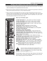
Page 23: ...Press the Next button to move forward through the list of menu items that are available as shown on pages 22 and 23 or press the Previous button to move back to an item that you recently passed b Press the Select button if you wish to make a setting change to a menu item The menu item will flash to indicate that its setting is ready to be changed c Press Next to move forward or Previous to go back...

Page 24: ...y display within two seconds If the display reads uC 0 go to step 3 If the operator has previously been configured the Installer Menu must be accessed in order to reach the system configu ration menu items see step 3d at the top of this page 3 When turning on the power for a new machine the LCD display directly enters the Installer Menu at the uC __ menu item which is for selecting the user class ...

Page 25: ...ller adjustable from 7 99 seconds 7 Open interlock input or Time clock Open menu configurable 8 Free Exit vehicle detector 9 Disable Free Exit vehicle detector 10 Inside Obstruction vehicle detector Inside reversing loop 11 Outside Obstruction vehicle detector Outside reversing loop 12 Shadow Reset vehicle detector Shadow is for Swing gates only Reset function is for Arm gates 13 Edge Sensor one i...

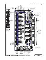
Page 26: ...TOR ACCESSORY DETECTOR USER RELAY PROGRAMMABLE RELAY RUN PROGRAMMABLE USER RELAY PROGRAMMABLE USER RELAY 15 AMP 15 AMP 15 AMP Hydraulic Directional Valve activates to OPEN Hydraulic Unloading or Quick Stop Valve activates when starting or stopping Clock Battery Optional Hy Security HY 5A Vehicle Detector Modules External Communication Port Processor heartbeat LED Blinks at a regular beat when norm...

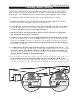
Page 27: ...ators route a shielded twisted pair with an internal ground wire between the electric control boxes and connect to the RS485 Dual Gate terminals in matching order on both machines In the RS485 shaded area connect the terminals for Master Com to Slave Com with the ground shield trace wire and connect the Master A to Slave A and the Master B to Slave B using the insulated twisted pair of wires 6 The...

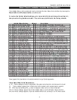
Page 28: ...st any specific need Once you have learned to navigate the menus as described in 2 on page 17 and how to change a setting the full range of features and choices of the Smart Touch Controller are available to use The User Menu contains the basic configuration items and the Installer Menu contains the more advanced menu items User Menu Options Default Description U1 Ct 0 Close timer setting 0 0 Clos...

Page 29: ...ly I17 Sr 1 IES reverse to open 1 0 IES reverses fully open 1 2 sec reversal only I18 PC 0 Set PEO PEC NO NC 0 0 Normally Open PE output 1 N C supervised I19 gC 0 Set Edge input NO NC 0 0 Normally Open Edge output 1 Normally Closed I20 tC 1 Time clock Interlock input 1 0 select Time Clock 1 select Open Interlock I21 or 1 OOLD detector function 1 0 pause closing only 1 enable reversing to open I22 ...

Page 30: ...ion This function is intended for highly secure facilities If it is enabled by setting the selection to 1 it will reinitiate a closure if a gate is somehow forced to open far enough that the close limit switch releases The Alert buzzer will sound immediately even if it had been turned off and the motor will restart to secure the gate fully closed If the gate is not fully closed within four seconds...

Page 31: ...t Sensor sensitivity This menu item is to adjust the sensitivity of the internal inherent sensor Available settings are 1 9 with 9 being the least sensitive Installer 9 SS 0 Inherent Sensor function This menu item is only available in UL class 4 operators and allows an option whereby the inherent sensor will only stop the gate Installer 10 LC 0 Leaf delay Close This menu item only appears if the o...

Page 32: ...r 21 or 1 OOLD Outside Obstruction loop detector function The default for this menu item is for full reversal when the OOLD is triggered The optional setting or_0 causes the gate to only pause when triggered Closure begins as soon as the loop is clear again Installer 22 ir 1 IOLD Inside Obstruction loop detector function The default for this menu item is for full reversal when the IOLD is triggere...

Page 33: ...e that it may need to be switched back for the interlock function If this alteration is needed go to the Installer Menu and set item tC _ to be tC_1 Connecting to an External Lock Mechanism An external solenoid lock or maglock can be controlled by the Smart Touch Controller to unlock just before gate motion begins 1 User relay 2 has been set by the factory to provide the necessary output for a sol...

Page 34: ...been open longer than a user selected period of time Adjustable from 0 delay then 15 seconds delay to 135 seconds delay in 30 second time increments 9 Safety Mode Alert output Activated when system is in the Safety Mode or the Entrapment Mode Safety Mode occurs upon an impact with an obstruction Entrapment Mode means the gate is stopped and occurs if the internal inherent sensor triggers while the...

Page 35: ...Select button Note you must push the Menu button for software version prior to h3 01 to change the display to a blinking adjustable value The following letters will be displayed on the left side to aid in knowing which setting is being made a Setting CL 1 minutes display ni 0 59 b Setting CL 2 hours display hr 0 23 c Setting CL 3 days display dA 1 31 d Setting CL 4 months display no 1 12 3 Make an...

Page 36: ...sor on leading edge and trailing edge Note All wheels must be covered Wheels and covers not shown for clarity Audio alarm Access controls at least six feetaway from gateand operator Stop and reset button Physical travel stop both ends Photo Eyes for both directions Attention This schematic view is not meant to recommend the only way to set up your configuration but to point out the various element...

Page 37: ...ge sensor device or the equivalent Type C Inherent adjustable clutch or pressure relief device Type D An actuating device requiring continuous pressure to maintain opening or closing motion of the gate Type E An inherent audio alarm which warns a minimum of 3 seconds before operation UL Usage Class Information The automatic vehicular operator must also be labeled as appropriate for both the type a...

Page 38: ...both the open and closing directions of gate travel must be guarded The UL 325 standard for automatic sliding gates specifically requires the following One or more non contact sensors photoelectric eyes shall be located where the risk of entrap ment or obstruction exists such as the perimeter reachable by a moving gate One or more contact sensors edge sensors shall be located at the leading edge t...

Page 39: ...vided in both directions of travel b Mount one or two edge transmitters Linear Model 3022 or equivalent onto the gate panel near the upper corner of the leading edge of the gate Both gate edges will function correctly if only one transmitter is used but wiring both edges to a single transmitter may be impractical or displeasing visually c Connect the edge s to the terminals in the edge transmitter...

Page 40: ... photo eyes will be required to function for both the open and closing directions of travel Mount the receiv ers on the left and right sides of the gate operator and the emitters just beyond the travel of the gate in both the full open and full closed positions of travel In some situations an additional photo eye should be installed on the public side of the gate The installation locations describ...

Page 41: ... Correct installation and alignment of a retro reflective photo eye and its reflector is important for a trouble free installation Any system operating at a range greater than 16 feet is more prone to false triggering due to dirty optics condensation or poor weather If care is taken in the initial mounting and alignment of the 3 inch reflector the chance of problems is greatly reduced Taking steps...

Page 42: ...one detector 3 In applications with multiple loops keep each loop at least six feet apart This avoids cross talk It is possible to have loops closer together by selecting different frequencies An advantage of using Hy Security model HY 5A detectors is that problematic cross talk is not possible 4 For greater sensitivity and less chance of false calls caused by the motion of the gate it is better t...

Page 43: ...ectors be used for free open and obstruc tion sensing logic only The exception is in parking applications with our HTG 320 operator where detectors may be also used to close the gate In applications employing our swing vertical lift or sliding gate operators closing logic cannot be used Because of their slower speeds closing logic is a poor choice for security gate systems Since there are several ...

Page 44: ...TEM OMIT EITHER THE FREE EXIT LOOP OR THE ENTRY CONTROL DEVICES GATE STARTS TIMING TO CLOSE AS TIMER IS ADJUSTABLE FROM 1 TO 99 SECONDS DIMENSION A 6 TO 20 FEET DIMENSION B 6 TO 8 FEET DIMENSION C MAINTAIN 4 FEET DIMENSION D MAINTAIN 5 FEET BETWEEN LOOP AND EDGE OF ROADWAY NO VEHICLE CAN PASS THROUGH SUCH A SMALL AREA AND ESCAPE DETECTION DIMENSION E LOCATED FOR CONVENIENCE OF USE FREE EXIT LOOP E...

Page 45: ...LCD display e Smart Touch will report loop malfunctions and store this data in its EEprom memory f Most detector or loop faults that could occur are reported and displayed on the LCD display There are four vehicle detector inputs available both on the main terminal strip and as direct plug in modules The vehicle detector inputs are for the following functions 1 Free Exit Loop Detector ELD 2 Outsid...

Page 46: ...s The frequency can also be manually selected if needed see the installer menu options 7 Sensitivity is the only adjustment on the detector itself Generally sensitivity does not need to be increased unless the loop is large loop or there are multiple loops connected to one detector Do not exceed more than 200 sq ft of loop area to one detector The rotary switch for sensitivity has eight settings w...

Page 47: ... power to the detector Polarity does not matter if the detector is a 24 AC model If a DC detector is used pin 1 is on a DC detector and pin 2 is 4 Connect the output pin 6 to the common Buss on the power supply and the output pin 5 to one of the four detector inputs depending upon the detector function required on the Smart Touch Controller terminal strip 5 If multiple detectors are used join the ...

Page 48: ... The display will flash between F_xx which are the high digits then the low digits of the loop frequency counter For example F_05 3413 would represent a frequency of 53 413 Hertz The highest digit will probably be only a single digit because loop frequency is usually a five digit number between 20 000 to 80 000 Hertz Changing the Loop Frequency HY 5A detectors can never crosstalk but if for any re...

Page 49: ...function as mode 1 except the close timer is allowed to time out even with the Free Exit OOLD IOLD or Shadow detector inputs active If the close timer has counted to zero the gate will close when all detector inputs are clear Mode 3 Same functions of mode 1 however the close timer is forced to zero when both the OOLD IOLD are tripped simultaneously Additionally any other close inputs are memorized...

Page 50: ... the time an hour In the fall press 1h to set back an hour Setting the Time IMPORTANT If an ON time was programed that is earlier than the current time press once to turn the timer ON It does not look back to determine if it should be on or off after programing Up to 20 Programs are able to be entered at one time Reviewing Programs To review the programs at any time press Prog key Programs will ap...

Page 51: ...radio power wire together with one of the radio output wires into a 25 spade connector and connect to the COM terminal Connect the red wire to the 24V terminal and connect the other radio output contact wire to the spade marked OPEN Note that this terminal is the same as the 4 input terminal labeled Edge Sensor on the main control board Mount an external antenna onto the top of a fixed post of the...

Page 52: ... ones used to inflate sports equipment or bicycle tires 1 Remove hand pump from box Pull straight out to remove from mounting clips 2 Push threaded coupling attached to end of tubing into hand pump Do not screw or twist 3 Lock coupling in place by toggling the locking lever away from pump 4 Pump until gauge pressure indicates 50 PSI The clamp on the wheel should now be released and the gate can be...

Page 53: ... to drive an external solenoid lock device as well Adjustment of the Factory Solenoid Lock Operators equipped with our factory solenoid lock require a notch to be cut into the outer vertical face of the drive rail The notch location is determined in the field after the gate operator is func tioning properly Run the gate to its full closed position and note the location where the deadbolt pin strik...

Page 54: ...TIRE INTERNAL SOLENOID LOCK ASSEMBLY INCLUDING LOCK PIN PIVOTS DOWN AWAY FROM NOTCH WHEN DRIVE WHEEL TOGGLE ASSEMBLY IS DISENGAGED ALLOWING FOR BETWEEN THE NOTCH IN THE DRIVE RAIL AND THE LOCK BOLT MANUAL OPERATION IN CASE OF POWER FAILURE MANUAL RELEASE ADJUST HEIGHT OF SOLENOID LOCK TO ACHIEVE THIS RELATIONSHIP INTERNAL SOLENOID LOCK ELEVATION S18b FOR RELIABLE LOCKING NOTCH OUT A 3 WIDTH OF THE...

Page 55: ...Installation and Maintenance Manual 49 INTERNAL SOLENOID LOCK S26b UPPER DRIVE WHEEL DRIVE RAIL OUTLINE OF OPERATOR HOUSING LOWER DRIVE WHEEL ...

Page 56: ...ton is not used 4 Verify there are no Faults or Errors reported on the LCD display See table on next page 5 If the motor contactor chatters voltage drop due to undersized wires is the likely cause Check Appendix 9 for maximum allowable length of wiring runs vs wire size The pump is running but the wheels are slow or not turning at all Hydraulic pressure is between 0 700 PSI on the gauge 1 If the p...

Page 57: ...econds Loop detector active 5 minutes AL12 2 chirps sec every 15 seconds Maximum run Fault FAL1 1 chirp once every 15 seconds Photo eye Fault supervised FAL2 2 chirps sec once per minute Critical AC sag bad supply wire FAL3 2 chirps sec once per minute Directional motion Error Err1 3 chirps sec once per minute Disconnected IES Error Err2 3 chirps sec once per minute Loop detector failed Err3 3 chi...

Page 58: ...one inch of the filler port Replace the plug and wipe up any spilled oil If any oil is allowed to remain it will dry to a very sticky and messy consistency Cold Weather 1 Check that your reservoir is filled with our Uniflow high performance oil 2 Ice can partly or totally jam gate operation Check function by operating the gate manually Electrical Controls Before servicing turn off power disconnect...

Page 59: ...nels should be straightened or replaced 2 Normally the drive wheels will last for many years because they are designed to not slip on the rail The life of the wheels may be greatly shortened by any of these faults clamping spring not correctly adjusted operator misaligned in relation to gate panel badly warped gate panel or ex tremely stiff hardware 3 Verify that the red clamping spring is compres...

Page 60: ...on it will push on the base of the operator which will cause the upper drive wheel to lift and disengage from the drive rail For shipment a piece of wood was placed between the coupling nut and the chassis If the wood is still in place discard it If the drive rail has been installed at the correct height to the chassis the manual toggle release mechanism will equally spread both wheels away from t...

Page 61: ...urrent Observe special care when connecting the cables to the batteries that the polarity is correct The batteries are connected in a series circuit join the positive terminal from one battery to the negative terminal of the next battery Since this operator is intended to run on batteries control of the load is important Easier moving gates will drain less energy from the battery preserving capaci...

Page 62: ...t Touch Controller User Menu U4 provides four optional system configurations for 24 Volt DC battery type gate operators Since this is an uninterruptible power supply system the installer must decide depending upon customer preference what is to happen when the AC line power fails There are four functional choices provided in the User Menu item AP_ Setting 0 Type A The operator functions normally u...

Page 63: ...IMUM IF DRIVE UNIT 2 GA MINIMUM FOR 2 HP MODELS 6 GA MINIMUM FOR 1 HP MODELS 2 EA HEAVY GAUGE FOR MOTOR 4 EA 14GA MINIMUM FOR CONTROL PANEL 4 CONDUCTORS REQUIRED POWER SUPPLY WIRING TO DRIVE UNIT 4 BATTERY 170AH AS SHOWN 2 BATTERY 90AH 30 W X 30 H X 12 D D C POWER BATTERY PACKS GREATER THAN 10 FEET OPERATOR CONTACT FACTORY IF DISTANCE IS SHOULD BE LOCATED WITHIN 10 FEET OF WHEN POSSIBLE ELECTRICAL...

Page 64: ...ERATOR AS SHOWN FOUR 14GA WIRES TO CONTROL CIRCUIT CONNECT FROM LUG TERMINALS TO DC MOTOR TWO 6 GA MINIMUM FOR 222 DS OR 222 DE or TWO 2 GA MINIMUM FOR 222 DX INSTALL BATTERIES AS SHOWN OBSERVING POLARITY ALWAYS OBSERVE POLARITY CAREFULLY ALWAYS CONNECT RED WIRES TO AND BLACK WIRES TO EXCEPT FOR WIRES CONNECTING THE BATTERIES 24 VOLT FUSE 5 AMP LINE VOLTAGE FUSE 15 AMP 24V 100 A H BATTERY POWER A ...

Page 65: ...O GATE OPERATOR AS SHOWN FOUR 14GA WIRES TO CONTROL CIRCUIT CONNECT FROM LUG TERMINALS TO DC MOTOR TWO 6 GA MINIMUM FOR 222 DS OR 222 DE or TWO 2 GA MINIMUM FOR 222 DX INSTALL BATTERIES AS SHOWN OBSERVING POLARITY ALWAYS OBSERVE POLARITY CAREFULLY ALWAYS CONNECT RED WIRES TO AND BLACK WIRES TO EXCEPT FOR WIRES CONNECTING THE BATTERIES 24 VOLT FUSE 5 AMP LINE VOLTAGE FUSE 15 AMP 24V 170 A H BATTERY...

Page 66: ...LE PROJECTION MS14 REV DRAWN APPROVED CHECKED DATE DATE DATE 7 27 0 KERI ERN NUMBER ERN000010 5 16 00 DATE GREATER THAN 10 FEET OPERATOR CONTACT FACTORY IF DISTANCE IS SHOULD BE LOCATED WITHIN 10 FEET OF WHEN POSSIBLE ELECTRICAL ENCLOSURE ALIGNMENT OF ALL COMPONENTS ELECTRICAL ENCLOSURE WILL HELP ASSURE ONE SLAB TO SUPPORT OPERATOR AND ARE 4 MINIMUM POSTS AND HARDWARE ARE FOR PASSAGE OF ELECTRICAL...

Page 67: ...00 bar psi PUSH BUTTON STATION 250W FILL ONLY WITH HY SECURITY UNIFLOW HYDRAULIC OIL PART H004 BEFORE USING OTHER OILS CONSULT OPERATOR HANDBOOK NOTICE OPTIONAL BRAKE VALVES NOT ON 333MS MODEL CHECK VALVE VALVE PUMP AND ELECTRICAL PANEL 333MS 333E 333EX TYPICAL seattle washington TITLE THIRD ANGLE PROJECTION DRAWING NUMBER DATE APPROVED DATE DATE 05 08 00 DRAWN CHECKED D B 1 1 MS12 SHT OF DATE REV...

Page 68: ...es on the following page are based on copper wire and allow for a 5 voltage drop The ampere values shown are the service factor ampere rating maximum full load at continuous duty of the motor Always connect in accordance with the National Electrical Code article 430 and other local codes that may apply The maximum distance shown is from the gate operator to the power source assuming that source po...

Page 69: ...Installation and Maintenance Manual 63 Wire Size for Voltage Drop Over Distance ...

Page 70: ...L MINIMUM SLAB DIMENSIONS RECOMMENDED ARE 50 WIDE 20 FROM FRONT TO BACK AND 20 DEEP CHECK ALL LOCAL FROST CONDITIONS AND SOIL CHARACTERISTICS FOR EXACT REQUIREMENTS 14 5 8 00 1 25 10 0 10 0 1 25 6 50 8 00 2 00 43 0 2 00 5 00 444 OPERATOR COMPONENTS AND FOOTPRINT XS48 9 43 125 SIX ANCHOR BOLTS 1 2 x 6 ARE REQUIRED TO PROPERLY ANCHOR THE CHASSIS BASE AS SHOWN ABOVE CUTOUTS SHOWN ARE FOR ELECTRICAL F...

Page 71: ... 3 MOTOR MOUNT PIN 4 1 HYDRAULIC HOSES 3 3 LIMIT RAMP 4 7 POWER UNIT 3 6 4 8 FOR 222 X1 OPERATOR OR 444 XS SAME AS ABOVE WITH THE FOLLOWING EXCEPTIONS COMPONENTS ALL A C SLIDE TITLE 6 26 0 APPROVED DATE D B CHECKED DRAWN DATE DATE DRAWING NUMBER ERN NUMBER THIRD ANGLE PROJECTION SHT OF REV OPERATORS EXCEPT 111 LS seattle washington SS34A 1 1 DATE TOGGLE ASSY SEE DWG S24 FOR DETAILS QTY ITEM HMOMO ...

Page 72: ...WING NUMBER THIRD ANGLE PROJECTION SHT OF A REV TOGGLE ASSEMBY FOR seattle washington S24 1 1 DATE ALL SLIDE GATE OPERATORS MFACS 006 020 MFACS 006 032 MSLDU 008 C MFALP 006 4 EA MSLDU 009 A MSLDU 008 B MSLDU 009 MFAAT 006 088 MSLSP 005 2 5 MSLDU 008 D MFACN 006 018 MSLDU 006 MFACS 006 016 2 EA MFAWA 006 MFAIP 006 ERN NUMBER ...

Page 73: ... HY Wheel Clamping Assembly MSLDU 070 CAST 10 Ga Steel Chassis Pressure Gauge E Manifold HMAMA 222 BVK Electric Motor On Off Switch ESWDI 050 3P Controller Board ESR00018 SA AC models or ESR00018 SD DC models AWOG with Manifold EX X1 CX 444 only Power Units are Detailed by Operator Series on next two pages Display Board ESR00019 Power Supply ESR00016 AC AC models or ESR00016 DC DC models Transform...

Page 74: ...EA 2 8 ETRTR 024 075 1 EA 2 9 ESWMC TEL 1810 1 EA or ESWMC AB1624 1 EA 2 10 ESR00038 1 EA 2 11 ESR00019 1 EA 2 12 ESWDI 050 3P 1 EA 2 13 ESR00039 1 EA 2 14 EECDE HY5A 1 EA C I R C U I T BR E A K E R 2 10 MEMBRANE SWITCH 2 11 DISPLAY BOARD 2 1 AC 2 2 DC POWER SUPPLY SMART TOUCH CONTROLLER 2 6 AC MODELS 2 7 DC MODELS 2 3 2 5 11 PIN SOCKET MOUNTING RAIL CONTACTOR 2 9 2 4 TERMINAL 5 POLE 2 8 CONTROL T...

Page 75: ...il HVASO 040 Reservoir HRSRS 004 Coupler MPTCO 010 9T Electric Motor SS CF E CE 60 Hz 1 phase EMOB6 215 1 0E 3 phase EMOB6 235 1 0T 50 Hz 1 phase EMOB5 215 1 0E 3 phase EMOB5 236 1A0S Quick Stop Valve HVAQS 001 C Quick Stop Coil HVASO 050 DC Electric Motor DS DE EMOSO DC6 2 02 DC Motor Starter ESWMC 075 MERC Capacitor 1 phase only EMOCP 645 774 Start Switch 1 phase only EMOSS 012 Check Valve HVACK...

Page 76: ...O 010 9T Electric Motor EX CX X1 60 Hz 1 phase EMOB6 215 2 0E 3 phase EMOB6 235 2 0T 50 Hz 1 phase EMOB5 215 2 0E 3 phase EMOB5 234 2A0S 5HP 444 XS 60Hz 1 phase EMOB6 215 5 0W 3 phase EMOB6 236 5 0C 50Hz 3 phase EMOB5 236 5 0C Quick Stop Valve HVAQS 001 C AWOG Hose HMAAC 111 H Quick Stop Coil HVASO 050 EX CX DX and 444 XS Models Relief Valve HVARE LAN DX Electric Motor EMOSO DC6 2 02 DX Motor Star...

Page 77: ...TAT 2 16 OPTIONAL FOIL HEATER item number qty 2 0 ESWCB 030 060 1 ea 2 1 ESWCB 030 120 1 ea 2 2 ESWCB 030 150 1 ea 2 3 ESWDI 067 DCEX 1 ea 2 4 ECOTS 1102 1 ea 2 5 EENEN HO1 3030 1 ea 2 6 EENEN HO1 4230 1 ea 2 7 EDCBY 12B 090 2 ea 2 8 EDCBY 06V 170 4 ea 2 9 ECOTS 005 1 ea 2 10 ESWFU 010 15 1 ea 2 11 ESWFU 010 05 1 ea 2 12 ESWFU 001 BLK 1 ea 2 13 EDCBC 024 025 1 ea 2 14 EDCFV 001 1 ea 2 15 EACTH B10...

Page 78: ...ll other incidental costs are NOT covered by this warranty There are no obligations or liabilities on the part of Hy Security Gate Inc for consequential damages arising out of or in connection with the use or performance of this product Hy Security Gate Inc assumes no responsibility for other indirect damages with respect to loss of property profit or revenue This Limited Warranty is valid only in...

Reviews: