G1E Programming Manual
43
Access Control Telephone – ACP
z
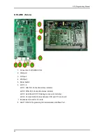
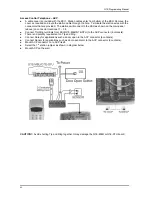
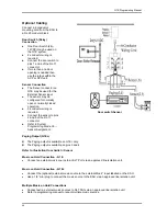
A cable cover is provided with the KSU. Station cables enter from bottom of the KSU. Remove the
cover as required and route the station cable through the hole. Terminate the station wires with the
connectors that are provided. The stations will connect to the KSU as shown on the main panel
(above) on connector locations 11 – 38
z
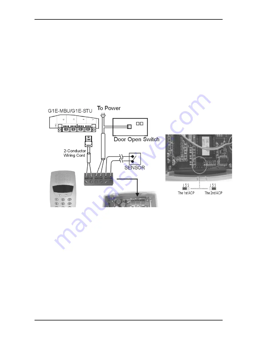
Connect Tip/Ring terminals from KSU(G1E-MBU/G1E-STU) to the ACP connector (6 contacts).
z
There is no polarity requirement on Tip and Ring.
z
Connect Relay for applications such as door open to the ACP connector (6 contacts).
z
Connect Sensor for applications such as door open alarm to the ACP connector (6 contacts).
z
Mount ACP connector on to ACP itself.
z
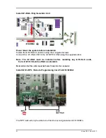
Select the 1
st
station jumper as shown in diagram below.
z
Mount ACP on the wall.
CAUTION!:
Avoid shorting Tip and Ring together. It may damage the G1E-MBU or G1E-STU board.
Summary of Contents for G1E
Page 16: ...Issue 3 3 2 April 2011 ...
Page 26: ......
Page 30: ...14 Issue 3 3 2 April 2011 G1E Main Equipment with MSC VMC 2 TKU s 2 STU s Installed ...
Page 31: ...G1E Programming Manual 15 G1E Main Equipment ...
Page 69: ...G1E Programming Manual 53 PROGRAMMING INFORMATION ...
Page 74: ...58 Issue 3 3 2 April 2011 ...
Page 75: ...G1E Programming Manual 59 PROGRAM MODES ...
Page 117: ...G1E Programming Manual 101 07 Reserved 08 Reserved ...
Page 119: ...G1E Programming Manual 103 07 Reserved 08 Reserved ...
Page 121: ...G1E Programming Manual 105 07 Reserved 08 Reserved ...
Page 127: ...G1E Programming Manual 111 ...
Page 169: ...G1E Programming Manual 153 ...
Page 171: ...G1E Programming Manual 155 05 Reserved 06 Reserved 07 Reserved 08 Reserved ...
Page 218: ......

