background image


5.  Configure FTP transfer not to use the 

“Passive transfer”  


6.  Click OK to make the connection and you will see the same information for the Remote Site as 

below. 


Summary of Contents for GDS-600

Page 1: ...The Business Telephone Specialists GDS 600 Digital Telephone System ISDN Digital Telephone System Installation Manual V4 1 1 ...

Page 2: ...makes no warranty or representation either express or implied with respect to merchantability or fitness of its products for a particular purpose 2005 2014 Auto Telecom Company Ltd This document or any parts thereof are not to be reproduced or transmitted in any form or by any means electronic or mechanical including photocopying recording or information storage and retrieval systems for any purpo...

Page 3: ...nt and shall be easily accessible 9 This product is equipped with a three wire grounding type plug this plug will only fit into a grounding type power outlet This is a safety feature If you are unable to insert the plug into the outlet contact your electrician to replace your obsolete outlet Do not defeat the safety purpose of the grounding type plug 10 Do not allow anything to rest on the power c...

Page 4: ... EASY INSTALLATION 3 EASY MAINTENANCE 3 FLEXIBILITY OF SYSTEM APPLICATIONS 3 VARIED EXTENSION ALTERNATIVES 3 FULL ISDN FEATURES 4 LIQUID CRYSTAL DISPLAY 4 MECHANICAL SPECIFICATIONS KEY SERVICE UNIT SINGLE CABINET 7 MECHANICAL SPECIFICATIONS BATTERY BACK UP HOUSING 7 ENVIRONMENTAL SPECIFICATIONS 7 FEATURES 8 SYSTEM FEATURES 8 STATION FEATURES 9 OPTIONAL FEATURES 9 PARTS PERIPHERALS 10 SYSTEM MODULE...

Page 5: ...D320 80 PORTS G2 EMD80 34 D GDS600 640 PORTS 80 PORTS G2 MMD640 80 PORTS G2 EMD80 36 G2 MSU MULTI SERVICE CARD 39 G2 VMU VOICE MAIL SERVICE CARD 40 G2 STU DIGITAL STATION CARD 40 G2 STU2 DIGITAL STATION CARD 40 G2 SLU ANALOG STATION CARD 41 G2 HSU 44 4 DIGITAL 4 ANALOGUE CARD 41 G2 ASU 8 ANALOGUE KEYPHONE INTERFACE CARD 41 G2 TKU 4 PORT CO LINE CARD AND G2 CIC CALLER ID CARD 42 G2 TKU2 8 PORT TRUN...

Page 6: ...56 INCORRECT WIRING FOR DIGITAL PHONES 57 SINGLE LINE TELEPHONE CONNECTED TO G2 SLU 58 SINGLE LINE TELEPHONE CONNECTED TO DK SLD OBSELETE 58 CO PABX CONNECTIONS 59 ISDN S T CONNECTIONS 59 OPTIONAL CABLING 62 DOOR SWITCH RELAY CONNECTION 62 SENSOR CONNECTION 62 PAGING CONNECTION 62 MUSIC ON HOLD CONNECTION 62 RS232 PORT CONNECTION 63 POWER ON AND OPERATIONAL TEST 64 OPERATIONAL TESTS 64 SPECIAL IMM...

Page 7: ...ate notice in writing to allow the customer an opportunity to maintain uninterrupted service Radio Frequency Interference This equipment generates and uses radio frequency energy and if not installed and used properly and in strict accordance with the manufacturer s instructions may cause interference to radio and television reception It has been type tested and found to comply with the limits for...

Page 8: ...ntial applications At the forefront of the system design is a universal concept to adapting and connecting with a variety of communications devices Productive HYBREX Digital Key Telephones offer thoughtfully designed productive feature access to keep you connected with one another and customers Auto Telecom technology leads the industry in providing for compatibility with devices such as fax machi...

Page 9: ... Back Up Customer data is backed up when the power is turned off and there is no battery to replace Battery Back Up System Operation GDS 600 systems can be equipped with an optional battery back up which keeps the system operational for a minimum 1 hour in the case of a commercial power failure Customer Care Programming Customers and service personnel can easily communicate and perform programming...

Page 10: ...s total comprised of 2 rows by 16 characters each 10 user defined buttons are available The DK6 Series Telephone Model DK6 21 DK6 31 are equipped with a large easy to read LCD display The LCD is 32 characters total comprised of 2 rows by 16 characters each 36 user defined buttons are available on the DK6 21 and 12 on the DK6 31 The IP38 61 phone based on the DK6 style is an IP only phone equipped ...

Page 11: ...GDS 600 General Description 5 HYBREX Telephone Models DK1 21 DK1 31 Obsolete ACP Plastic obsolete ACP Steel DK DPU1 Obsolete ACP40 ACP30 DK2 21 DK2 21 DK2 DSS DK3 33 DK3 21 ...

Page 12: ...Issue 4 1 1 October 2014 DK6 21 DK6 31 DK6 33 DK7 21 IP 38 61 DK9 25 DK9 15 DK9 DSS ...

Page 13: ...1 Pair 2 wires Door Switch Twisted 1 Pair 2 wires External Sensor Twisted 1 Pair 2 wires External Music Source Twisted 1 Pair 2 wires Single Line Telephone Twisted 1 Pair 2 wires Mechanical Specifications Key Service Unit single cabinet CABINET DIMENSIONS 357 mm W 126 mm D 436 mm H 14 1 4 96 17 2 WEIGHT 17 Kg Configuration 4 x 8 37 4 lbs Mechanical Specifications Battery Back Up Housing 2 required...

Page 14: ...lan 2 3 or 4 Digit Flexible Time Format 12 24 Hour Forced Account Code Assignment Intercom Intercom Single Digit Assignment Intercom Ring Voice Select Intercom Dialing Restriction ISDN Call Charge Metering Information Caller Identification Direct Inward Dialing Call Forward Internal External Call Waiting MSN Multiple Subscriber Number Sub addressing User to User Signaling Host PABX Access Hot line...

Page 15: ...en Loop Timed Flash Hands free Answer Back Hearing Aid Compatibility Headset Compatibility Hold Exclusive System Hold Recall I Hold Indication I Use Indication Intercom Intercom ring voice interchange Intercom Step Call Intercom Voice Announce Last Number Redial Message Waiting Multi Language Display On Hook Dialing Prime Line Select Privacy Privacy Release Private Line Pulse Tone Conversion Ring ...

Page 16: ...XU Interface Auxiliary Unit Expansion PCM streams for G2 EMD80 G2 IPU2 G2 1648 Main CPU Controller G2 128 144 160 320 640 Interface Control Card G2 MSU Multi Service Card External Paging Relay Sensor RS232 MODEM Interface Door Phone External MOH Interface G2 TKU Trunk Card 4 CO lines G2 TKU2 Trunk Card 8 CO lines Hot swap G2 PIU ISDN PRI Interface 23 30 Channels Maximum G2 PIU T1 T1 Interface 23 C...

Page 17: ...ree Bluetooth wireless headset 22 dual color keys and 17 function keys for feature access DSS CO Lines and speed dial DK1 21 Multifunction Key Telephone Includes 32 character LCD display speakerphone handsfree headset jack 20 dual color keys and 14 function keys for feature access DSS CO Lines and speed dial DK3 21 Multifunction Key Telephone Includes 32 character LCD display speakerphone 10 dual ...

Page 18: ...nit which includes Power Supply Unit G2 PWU Main KSU G2 MMD m G2 MMD G2 EMD CPU Unit G2 MPU G2 IPU Multi Service Unit G2 MSU Interface Auxiliary Unit G2 IXU Optional Expansion Cards Trunk Card G2 TKU TKU 2 G2 SIU G2 PIU VOIP card G2 VIU G2 ITU Digital Station Card G2 STU four digital twin port circuits G2 STU2 8 Digital ports G2 ASU Analogue Keyphone 8 Circuit Card G2 ISU VOIP Station Card Single ...

Page 19: ...ounded outlet plug Input power Line capacity requirements 10 amperes SURGE PROTECTION A Surge Protector is recommended on the dedicated AC line VENTILATION AND TEMPERATURE Humidity 10 to 95 relative non condensing Temperature 32 to 113 0 to 45 EARTH GROUND A proper ground connection 14 AWG SERVICEABILITY Lighting conditions and working space adequate for future service Equipment Requirements Unpac...

Page 20: ... is adequate room for the future system expansion and that the connecting power cable between the power mains and the KSU The same applies for the battery back up unit Power Source Dedicated Power Source The power cord must be connected to a dedicated AC outlet Be sure that the third wire earth ground of the AC circuit is connected to a good electrical ground If a music source is installed it must...

Page 21: ... time and extra care to assure the printed circuit cards are properly aligned After installing each option and expansion card perform a visual inspection to assure the printed circuit card is installed properly 1 Remove the 4 screws located at the corners of the cabinet and lift the front cover off 2 Install the specific cards into the dedicated slots of G2 MBU as below card introduction ...

Page 22: ...WU 2 Fan power input 3 PIN 3 G2 MPU2 G2 MPU4 G2 MPU8 slot 4 LED1 Power LED of system Steady on when power is ON 5 JP1 Reset jumper for flash memory 6 VMU slot 7 TKU Slot 2 3 setting Jumper 8 MSU slot 9 G2 IPU2 slot 10 STU SLU 1 slot 11 STU SLU 2 slot 12 STU SLU 3 slot 13 STU SLU 4 slot 14 TKU 1 slot 15 TKU 2 slot ...

Page 23: ... Cabinet position selection 7 Power LED Solid red when power on 8 VMU 1 slot 9 VMU 2 slot 10 MSU slot 11 G2 IPU2 Slot 12 STU SLU 1 slot 13 STU SLU 2 slot 14 STU SLU 3 slot 15 STU SLU 4 slot 16 STU SLU 5 slot 17 SLU slot 6 18 TKU SIU PIU 1 slot 19 TKU SIU 2 slot 20 TKU3 slot 21 TKU4 slot Power Failure Transfer Port Mapping TKU CN18 CN19 CN20 CN21 SLU the first 4 ports CN14 CN15 CN16 CN17 ...

Page 24: ...U 1 slot 9 CN4 VMU 2 slot 10 CN5 MSU slot 11 CN6 G2 IPU slot 12 IXU Slot 13 CN12 STU SLU HSU ISU ITU 1 slot 14 CN13 STU SLU HSU ISU ITU 2 slot 15 CN14 STU SLU HSU ISU ITU3 slot 16 CN15 STU SLU HSU ISU ITU 4 slot 17 CN16 STU SLU HSU ISU ITU 5 slot 18 CN17 TKU SIU PIU 1 slot STU SLU HSU ISU ITU 6 Slot 19 CN18 TKU SIU 2 slot STU SLU HSU ISU ITU 7 Slot 20 CN19 TKU 3 slot STU SLU HSU ISU ITU 8 Slot 21 ...

Page 25: ...reen slow MPU2 is working normally B Flash red slow Software of G2 MPU2 is upgrading from TCP IP LAN connection C Flash green red slow G2 MPU2 is sync with IPU2s D Flash green red fast G2 MPU2 is upgrading the main software into the Flash Memory System must not be turned off at this stage or the system cannot be rebooted 7 Reset button Note The minimum level of G2 MBU to work with G2 MPU2 is G2 MB...

Page 26: ...hes slowly LED3 Heartbeat status normally a red light flashes slowly LED2 LAN port status LED1 xxxxx 7 Shut Down button Press 2 seconds and then see It is now safe to power down on display of DK phone to safely power down the system Note MUPN2 begins to work in 50 seconds after power On During start up process Red LED4 and Green LED3 flash quickly The minimum level of G2 MBU to work with G2 MPUN2 ...

Page 27: ...U4 8 LED Heart Bead A Flash green slow MPU4 is working normally B Flash red slow Software of G2 MPU4 is upgrading from TCP IP LAN connection C Flash green red slow G2 MPU4 is sync with IPU2s D Flash green red fast G2 MPU4 is upgrading the main software into the Flash Memory System must not be turned off at this stage or the system cannot reboot 9 Reset button Note The minimum level of G2 MBU to wo...

Page 28: ...2 IXU in the 1 st cabinet 2 Expansion connector 2 for G2 IXU in the 2 nd cabinet 3 Expansion connector 3 for G2 IXU in the 3 rd cabinet 4 Expansion connector 4 for G2 IXU in the 4 th cabinet 5 CF card for programming data 6 Connector for the flat cable to G2 MPU4 ...

Page 29: ... power down on display of DK phone to safe power down the system 7 Connector for the flat cable to G2 MXUN8 8 Reset button 9 LED Heart Bead LED4 Main Loop normally a green light flashes slowly LED3 Heartbeat status normally a red light flashes slowly LED2 LAN port status LED1 xxxxx Note MUPN4 begins to work 50 seconds after power On During start up process Red LED4 and Green LED3 flash quickly The...

Page 30: ...xpansion connector 2 for G2 IXU in the 2 nd cabinet 3 Expansion connector 3 for G2 IXU in the 3 rd cabinet 4 Expansion connector 4 for G2 IXU in the 4 th cabinet 8 Connector for the flat cable to G2 MPUN4 GDS600 320 ports 80 ports G2 MMD320 80 ports G2 EMD80 80 ports G2 EMD80 80 ports G2 EMD80 ...

Page 31: ...PU2 in the 8 th cabinet 9 RS232 port 10 Factory Test connector 11 Connector for the flat cable to G2 MXU8 12 LED Heart Bead A Flash green slow MPU8 is working normally B Flash red slow Software of G2 MPU8 is upgrading from TCP IP LAN connection C Flash green red slow G2 MPU8 is sync with IPU2s D Flash green red fast G2 MPU8 is upgrading the main software into the Flash Memory System is prohibited ...

Page 32: ...2 IXU in the 3 rd cabinet 4 Expansion connector 4 for G2 IXU in the 4 th cabinet 5 Expansion connector 5 for G2 IXU in the 5 th cabinet 6 Expansion connector 6 for G2 IXU in the 6 th cabinet 7 Expansion connector 7 for G2 IXU in the 7 th cabinet 8 Expansion connector 8 for G2 IXU in the 8 th cabinet 9 CF card for programming data 10 Connector for the flat cable to G2 MPU8 ...

Page 33: ...IPU2 in the 8 th cabinet 9 RS232 port 10 Shut Down button Press for 2 seconds and see It is now safe to power down on display of DK phone to safely power down the system 11 Connector for the flat cable to G2 MXUN8 12 Reset button 13 LED Heart Beat LED4 Main Loop normally a green light flashes slowly LED3 Heartbeat status normally a red light flashes slowly LED2 LAN port status LED1 xxxxx Note MUPN...

Page 34: ...3 rd cabinet 4 Expansion connector 4 for G2 IXU in the 4 th cabinet 5 Expansion connector 5 for G2 IXU in the 5 th cabinet 6 Expansion connector 6 for G2 IXU in the 6 th cabinet 7 Expansion connector 7 for G2 IXU in the 7 th cabinet 8 Expansion connector 8 for G2 IXU in the 8 th cabinet 9 Connector for the flat cable to G2 MPUN8 GDS600 640 ports 80 ports G2 MMD640 80 ports G2 EMD80 x 7 ...

Page 35: ...Unit 1 SW1 Reset button 2 JP2 Terminators Keep it at Off position always Default 3 HDLC controller for bus expansion of multi cabinet 4 LED1 Heart beat LED 5 CN6 connector for expanding cabinet 6 CN5 connector for expanding cabinet 64 port only 7 CN9 LCD connector ...

Page 36: ... Install G2 MPU2 in the MPU LMU slot of the 1 st cabinet 4 The IPU should be a G2 IPU2 HDLC chip on U17 and installed in the IPU slot of each cabinet Note The G2 IPU2 is for multi cabinet use The G2 IPU is only for single cabinet use 5 Install G2 IXU in the IXU slot of the 2 nd cabinet G2 EMD80 6 Connect the expansion cable short red one between G2 MPU2 to the G2 IPU2 in the 1 st cabinet as below ...

Page 37: ... G2 MPU2 and the G2 IXU in the 2 nd cabinet 8 Connect the expanding cable long blue one between the G2 IPU2 in each cabinet 9 Install all other interface cards in cabinets 10 Power on the first cabinet first 11 Power on the 2 nd cabinet immediately after OR at the same time as cabinet 1 ...

Page 38: ...e G2 MPU2 in the MPU LMU slot of the 1 st cabinet 4 The IPU should be a G2 IPU2 HDLC chip on U17 and installed in the IPU slot of each cabinet Note The G2 IPU2 is for multi cabinet use The G2 IPU is only for single cabinet use 5 Install the G2 IXU in the IXU slot of each cabinet G2 MMD80 and G2 EMD80 6 Connect the expansion cable short red one between the G2 MPU2 and the G2 IXU in the 1 st cabinet...

Page 39: ...G2 MPU2 and the G2 IXU in the 2 nd cabinet 8 Connect the expansion cable long blue one between the G2 IPU2s in each cabinet 9 Install all other interface cards in cabinets 10 Power on the first cabinet first 11 Power on the 2 nd cabinet immediately after Or at the same time as cabinet 1 ...

Page 40: ...3rd cabinet For the 4th cabinet 3 Install the G2 MPU4 in the MPU LMU slot of the 1 st cabinet 4 Install the G2 MXU4 in the first VMU slot of the 1 st cabinet 5 Connect the flat cable between the G2 MPU4 and the G2 MXU4 as below 6 The IPU should be a G2 IPU2 HDLC chip on U17 and installed in the IPU slot of each cabinet Note The G2 IPU2 is for multi cabinet use The G2 IPU is only for single cabinet...

Page 41: ...on cable long red 4 from the G2 MXU4 and the G2 IXU in the 4th cabinet as below 9 Connect the expansion cable long blue 2 between the G2 MPU4 and the G2 IPU2 in the 2 nd cabinet Connect the expansion cable long blue 3 between the G2 MPU4 and theG2 IPU2 in the 3rd cabinet Connect the expansion cable long blue 4 between the G2 MPU4 and the G2 IPU2 in the 4th cabinet 10 Install all other interface ca...

Page 42: ... the 1 st cabinet For the 2 nd cabinet For the 3rd cabinetFor the 4th cabinet For the 5 th cabinet For the 6 th cabinet For the 7 th cabinet For the 8 th cabinet 3 Install theG2 MPU8 in the MPU LMU slot of the 1 st cabinet 4 Install the G2 MXU8 in the first VMU slot of the 1 st cabinet 5 Connect the flat cable between the G2 MPU8 and the G2 MXU8 as below ...

Page 43: ...h cabinet G2 MMD640 and G2 EMD80 8 Connect the expansion cable short red 1 from the G2 MXU8 to the G2 IXU in the 1 st cabinet as below Connect the expansion cable long red 2 from the G2 MXU8 to the G2 IXU in the 2 nd cabinet as below Connect the expansion cable long red 7 from the G2 MXU8 to the G2 IXU in the 7 th cabinet as below Connect the expansion cable long red 8 from the G2 MXU8 to the G2 I...

Page 44: ...Connect the expansion cable long blue 8 from the G2 MPU8 to the G2 IPU2 in the 4 th cabinet 10 Install all other interface cards in cabinets 11 It is preferred to switch on all cabinets simultaneously OR 12 Power on the 2 nd 3 rd 4 th 5 th 6 th 7 th 8 th cabinet 13 Power on the first cabinet 14 Note The attached expansion cables 4 Short red expansion cable 5 Long red expansion cable 6 Long blue ex...

Page 45: ...external paging devices This is unlikely to be needed for most equipment 1 Grounding Jumper 2 MODEM connector for the external MODEM connection to the system 3 RS232 connector 4 Relay Sensor External Paging connector 5 CN3 Door Phone Interface for DPU05 6 CN2 External Music on Hold Interface ...

Page 46: ... recommended that all extensions are home run back to individual inner and outer pairs directly on the DDK connector G2 STU2 Digital Station Card Install the G2 STU2 card in STU1 STU SLU2 STU SLU5 slot of the G2 MBU The STU2 card has 8 individual digital ports It is necessary that all extensions are home run back to individual inner and outer pairs directly on the DDK connector Digital phones can ...

Page 47: ...U SLU2 STU SLU5 SLU6 slot of the G2 MBU G2 ASU 8 Analogue Keyphone Interface Card The G2 ASU 44 card has 8 circuits for connecting Analogue KeyPhones from the Hybrex BX range of telephone systems The Minimum software level is G3 E050H and Wobg The G2 ASU Card will support KPU AK series 1 and AK Series 2 phones with a minimum 95 functionality The G2 ASU will not be available as an add on to existin...

Page 48: ...f G1 CIC card for G2 use Install the G1 CIC card on CN6 CN7 of G2 TKU card Mis alignment could damage both cards or the system CN6 CN7 G1 CIC D G1 CIC F CN2 CN3 G1 MDC 12 16 G2 TKU2 8 Port Trunk Card and G2 CIC 2 Caller ID Card Install the G1 CIC card on the G2 TKU2 optional Install the G2 TKU2 card in the TKU1 TKU2 TKU3 TKU4 TKU5 slots of the G2 MBU The G2 TKU2 can be hot swapped if system softwa...

Page 49: ...U4 TKU5 slots of the G2 MBU VIU cards can be either SIP or MGCP depending on the firmware installed G2 VMU Voice Mail Unit Install the G2 VMU card in the VMU slots of the G2 MBU only There are 2 VMU slots in 64 port and 80 Port Cabinets The 1Gb version VMU uses onboard Flash memory rather than a CF card type storage ...

Page 50: ...SP daughterboard that increases the channel capacity 3 Reset Button Pressing this button will restart the AMS card 4 WAN Port Connection to a Switch or a Hub 5 LAN Port 6 Attached Memory Card 7 The Bus Connector that provides link to the GDS MBU The AMS can only be installed in dedicated VMU slots The minimum MBU version to support the G2 AMS is 64 Port MBU 1 D 80 Port MBU1 1 7 40 Port MBU2 1 B ...

Page 51: ...in any slot in a GDS system that has an extension slot connector The G2 ITU8 and G2 ITU16 have a daughterboard that provides more DSP processors for the extra Codec channels Changing the Daughterboard requires changing the card firmware If a G2 ITU16 is used the next slot down in the cabinet must be left vacant The card model and code version will be stated on the FlashROM label ...

Page 52: ...8 channel versions initially It installs in any slot in a GDS system that has an extension slot connector The G2 ISU8 has a daughterboard that provides more DSP processors for the extra Codec channels Changing the Daughterboard requires changing the card firmware The card model and code version will be usually be stated on the FlashROM label ...

Page 53: ...he internal ISDN device does not offer local power and needs DC feeding to work The related jumper of this internal ISDN interface needs to be set to on Caution 1 When this jumper is on users cannot loop S interface back to another T interface for testing purposes Otherwise it will damage this card 2 Incorrect jumper settings will also damage this card JP1 A B C JP2 A B C Bus Terminator ...

Page 54: ...must be left vacant Which limits the Extension capacity of the 64 port cabinet to 40 1 RJ 45 Connector Pin 1 2 for TX Pin 4 5 for RX 2 LED 2 For network Sync indication 1 Off No connection 2 Flash There is no sync 3 On Sync OK 3 LED 1 For the heart beat of the DSP chip 4 CN7 For test purposes 5 DSP chip for T1 E1 interface 6 CN4 CN5 Jumpers on CN4 are for the E1 interface and the ISDN PRI E1 inter...

Page 55: ... voltage When complete place the power supply cover back on the power supply Replace Fuses of Power Supply Replace Cover With the expansion and option cards installed and the battery insulator removed replace the cover and install the 4 screws removed earlier This concludes the installation of expansion and option cards ...

Page 56: ...X1 make certain that there is adequate room for its installation Make certain that the Battery Backup is mounted close enough to the Power Supply that the interconnecting cable between the Battery Backup and the Power Supply can connect Do Not Connect the Battery Backup at this time Do Not Connect the Battery Backup at this time Battery Backup should not be connected to the System power supply unt...

Page 57: ...rosive and may cause damage to the eyes or skin It may be toxic if swallowed 4 Exercise care in handling batteries in order not to short the battery with conducting materials such as rings bracelets and keys The battery or conductor may overheat and cause burns This product is defined as a secondary battery operated device As such the following instructions should also be read and followed 1 Charg...

Page 58: ... installation and minimizing service calls after installation Each extension MUST be wired individually back to the inner and outer pairs of the DDK connector on the station card and not paralleled external to the system with one pair back to the DDK connector This will ensure that the protection circuit on the output of the STU card will operate to isolate each extension from adverse effects of p...

Page 59: ...modular jack Ring with RED There is no polarity requirement on Tip and Ring 2 conductor wiring is required for DK1 Digital Key Telephones Open the overlay of the function key on DK1 telephone and select the 1 st or 2 nd station Dip switch to the right for the 1 st station Dip switch to the left for the 2 nd station CAUTION Avoid shorting Tip and Ring together It may damage the G2 MBU or G2 STU boa...

Page 60: ...rovided The stations will connect to the G2 STU of KSU 4 conductor wiring is required for the DK1 21H Digital Key Telephones from the Handset to the Wall socket Open the overlay of the function key on the DK1 21H telephone and select the 1 st station Connect the single line telephone from the phone box Connect Tip terminal with YEL terminal screws of the modular jack Ring with BLK CAUTION 1 Avoid ...

Page 61: ...ion wires on RJ45 connectors Each RJ45 connector connects 2 Analogue KeyPhones The Data pair of each connection is polarity conscious Loop resistance of each extension must not exceed 40 Ohms Analogue KeyPhones will not work at a similar distance to Digital or Analogue phones ...

Page 62: ...ts There is no polarity requirement on Tip and Ring Connect Relay for applications such as door open to the ACP connector 6 contacts Connect Sensor for applications such as door open alarm to the ACP connector 6 contacts Mount ACP connector on ACP itself Select the 1 st or 2 nd station Jumper as below diagram showed Mount ACP on the wall CAUTION Avoid shorting Tip and Ring together It may damage t...

Page 63: ...GDS 600 System Installation 57 Incorrect wiring for Digital Phones Do not use incorrect wiring as shown below as it will disturb the digital signal of digital telephones ...

Page 64: ...nt on Tip and Ring 2 conductor wiring is required for Single Line Telephones Single Line Telephone connected to DK SLD OBSELETE Terminate the station wires with the connectors that are provided The stations will connect to the G2 STU of the KSU Connect Tip terminal with GRN terminal screws of the modular jack Ring with RED There is no polarity requirement on Tip and Ring 2 conductor wiring is requ...

Page 65: ...e modular connector is required Connector PIN assignment Pin 1 2 7 8 are reserved Install remove the terminators by adjusting the jumper JP1 A B C and JP2 A B C on SIU card If there is no other ISDN device connected after the ISDN interface of SIU card when using point to multi point connection this ISDN interface port needs the terminator installed Otherwise remove the terminator Example The foll...

Page 66: ...nnection If the user has programmed the ISDN interface of SIU to a T Interface the wiring should be as follows S Interface Connection If the user has programmed the ISDN interface of SIU to a S Interface the wiring should be as the following ...

Page 67: ... Bus d2 100m 200m Length limitation by round trip delay 10us to 14us not by attenuation d3 Recommendation with a cord having a minimum length of 5m and not more than 10m 5m d3 10m Extended Passive Bus d4 500m 800m Length limitation by round trip delay 10us to 14us not by attenuation d5 25m 50m Length limitation between TEs by differential round trip delay of 2us ...

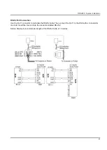
Page 68: ...lly closed operation 2 conductor wiring is required Connect the sensor to pins 2 and 5 of the RJ 11 connector Refer to System Programming Form 39 Sensor Assignment Paging Connection The Paging connector on the GDS 600 may be used for an External Paging input 2 conductor wiring is required Connect the amplifier to pins 3 and 4 of the RJ 11 connector Refer to Illustration Door Switch Sensor Paging c...

Page 69: ...nnection Use the RJ 11 connector to terminate the RS232 cable Then connect the RJ 11 to the KSU with a 6 conductor line cord Insert the line cord into the connector labeled RS 232 Notice Maximum recommended length of the RS232 cable is 15 metres ...

Page 70: ...eck each telephone and CO line to verify that outgoing lines are connected properly Check that intercom calls can be made from extension to extension WARNING DISCONNECT THE POWER SUPPLY FROM THE AC POWER SOURCE BEFORE WIRING OR CHANGING ANY WIRING Connect the Battery Backup AFTER AC power has been connected to the Power Supply Disconnect Battery Backup BEFORE disconnecting AC power from the Power ...

Page 71: ...GDS 600 System Installation 65 ...

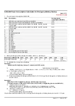
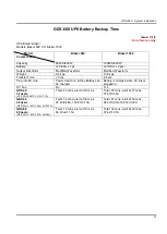
Page 72: ...t CA 0 05 0 10 0 12 0 15 0 20 0 40 0 60 1 00 1 50 Discharge time hours 20 10 8 6 4 2 1 0 5 30 min 0 33 20 min 3 To calculate the running time of batteries Example 1 GDS 64 and 16 digital key phones 1 cabinet and 2 STU cards A System power consumption GDS64 G2 STU x 2 16 x Digital phones 3 02 1 13 x 2 16 x 1 25 25 28w 40v 0 63A B b Discharge coefficient CA 0 63 7Ah x 0 5 0 18CA 0 5 Estimated batter...

Page 73: ...r Time 3ms 4 6 ms Plug into AC Line Power Switch on then Battery can be charged Battery is charged when AC line is plugged in DC Fan No Yes GDS 40 32 users G1 PWU 2 40V 1 1A 5V 1 1A Total 43 mins alert at 39 mins Total 85 mins alert at 77 mins 87 8V 0 46A GDS 64 48 users G2 PWU 1 40V 1 44A 5V 3 22A Total 33 mins alert at 30 mins 97 4V 0 68A 103 8V 0 75A Total 61 mins alert at 58 mins 94 5V 0 65A 1...

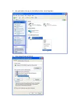
Page 74: ...0 5 2 Use straight Ethernet cable to connect the TCP IP LAN port of the MPU2 to a LAN or use a cross over Ethernet cable to connect the G2 MPU2 to a PC LAN card direct 3 Program the TCP IP environment on the PC as below Below is the example for Windows XP Professional A Click Start My Network Places B Click View Network Connections ...

Page 75: ...C Use right button of mouse to click LAN And then click Properties D Click Internet Protocol TCP IP ...

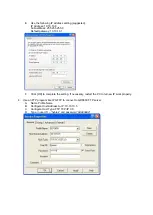
Page 76: ... 10 10 10 1 F Click OK to complete the setting If necessary restart the PC to let new IP work properly 4 Use an FTP program like WS FTP to connect to GDS600 FTP server A Name Profile Name B Configure Host Address to IP 10 10 10 5 C Configure Host Type FTP TCP IP 3 0 D Type in user ID hybrex and password dddddddd ...

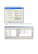
Page 77: ...5 Configure FTP transfer not to use the Passive transfer 6 Click OK to make the connection and you will see the same information for the Remote Site as below ...

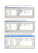
Page 78: ...button again 8 Login GDS 600 FTP server again and it will get the correct folder as below 9 If you receive the following screen with only 3 files shown in the remote site then it is likely that you will need to upgrade the loader before proceeding Abort the connection and Contact Tech Support ...

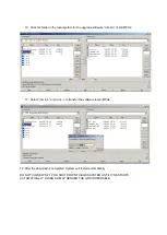
Page 79: ...m bin of G2 MPU2 11 Select rom bin and click to transfer the software to G2 MPU2 12 After the download is completed System will restart automatically DO NOT CLOSE WS FTP OR SHUT DOWN THE GDS SYSTEM UNTIL IT RESTARTS AUTOMATICALLY DOING SO MAY RENDER THE GDS INOPERABLE ...

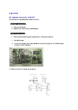
Page 80: ...ements 1 Personal Computer 2 6 Wire Line cord and RJ to DB9 Adapter Software requirements 1 Winloader EXE G1 Programming Software Windows Version 1 Start Winloader 2 Connect the RS232 cable from GDS MSU card to PC using RJ 11 to DB9 Female connector to PC COM port 3 RS232 connector for upgrade procedure ...

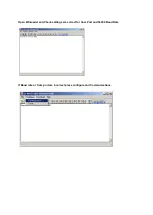
Page 81: ...Open Winloader and Check settings are correct for Com Port and 56000 Baud Rate If Baud rate or Com port are incorrect press configure and Communications ...

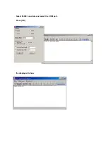
Page 82: ...Select 56000 baud rate and select the COM port Press OK the display will show ...

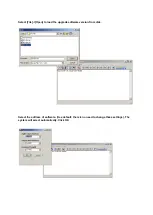
Page 83: ...Select File Open to load the upgrade software version from disk Select the address of software Use default there is no need to change these settings The system will select automatically Click OK ...

Page 84: ... the IPU Select Download to start the upgrade 9 11 Upgrade Successful press Finish to exit Winloader exe and disconnect the cable If you leave the cable connected and the program open the GDS will not restart if for some reason you turn it off and back on again ...

Page 85: ... SEC 2 SHIH CHUAN ROAD PAN CHIAO CITY TAIPEI TAIWAN http www hybrex com AUTO TELECOM AUSTRALIA PTY LTD Unit 7 3 Gibbes Street Chatswood NSW 2067 All data and specifications are subject to change without notice P N ...

Reviews: