7/8
IMM - KWADRA FL LED - AT_CT - PL_EN V01
INSTALLATION
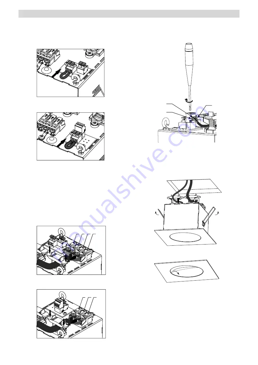
1. Unpack the luminaire after transport and verify its condition.
2. Cut a square hole in the ceiling with a side of 105 to 120mm.
3. Insert the jumper enabling the battery to the battery connector.
AT/SM/N
CT/NM
NOTE (for AT luminaire variant with lock connector):
If you use the emergency mode lock (see CONSTRUCTION) the same
polarity should be maintained when connecting the connectors of the
interlocks in parallel on the interlock connector of each luminaire. The
luminaire has a factory-shortened lock connector (emergency mode on).
4. Connect the power supply cables according to the appropriate wiring
diagrams, strip 7-8mm of wire copper insulation. Place the wires so that
the cover may be mounted without any obstacles. Pay special attention to
the luminaire supply voltage!
The luminaire may be through connected if permitted by national
regulations and the electrical project.
AT/SM/N
PE
2
1
N
CT/NM
PE
N
L
5. For the CT luminaire variant, connect communication wires
to the modules communication connector according to document
“Communication line installation manual”. Pay special attention that the
screen does not touch any metal part of the luminaire housing.
B
E
A
6. Push the spring holders up and slip the luminaire into the hole in the
ceiling. Pay attention to optics placement according to the escape route
(see OPTICS).
In order to sealing, it is necessary to apply silicone between the edge of
the luminaire and the ceiling (not required, when the degree of protection
IP20 is sufficient)
7. Remove the scratches protective film from the plastic pane.
8. Perform the commissioning procedure.


