5
Service, Maintenance and Hydraulic Settings
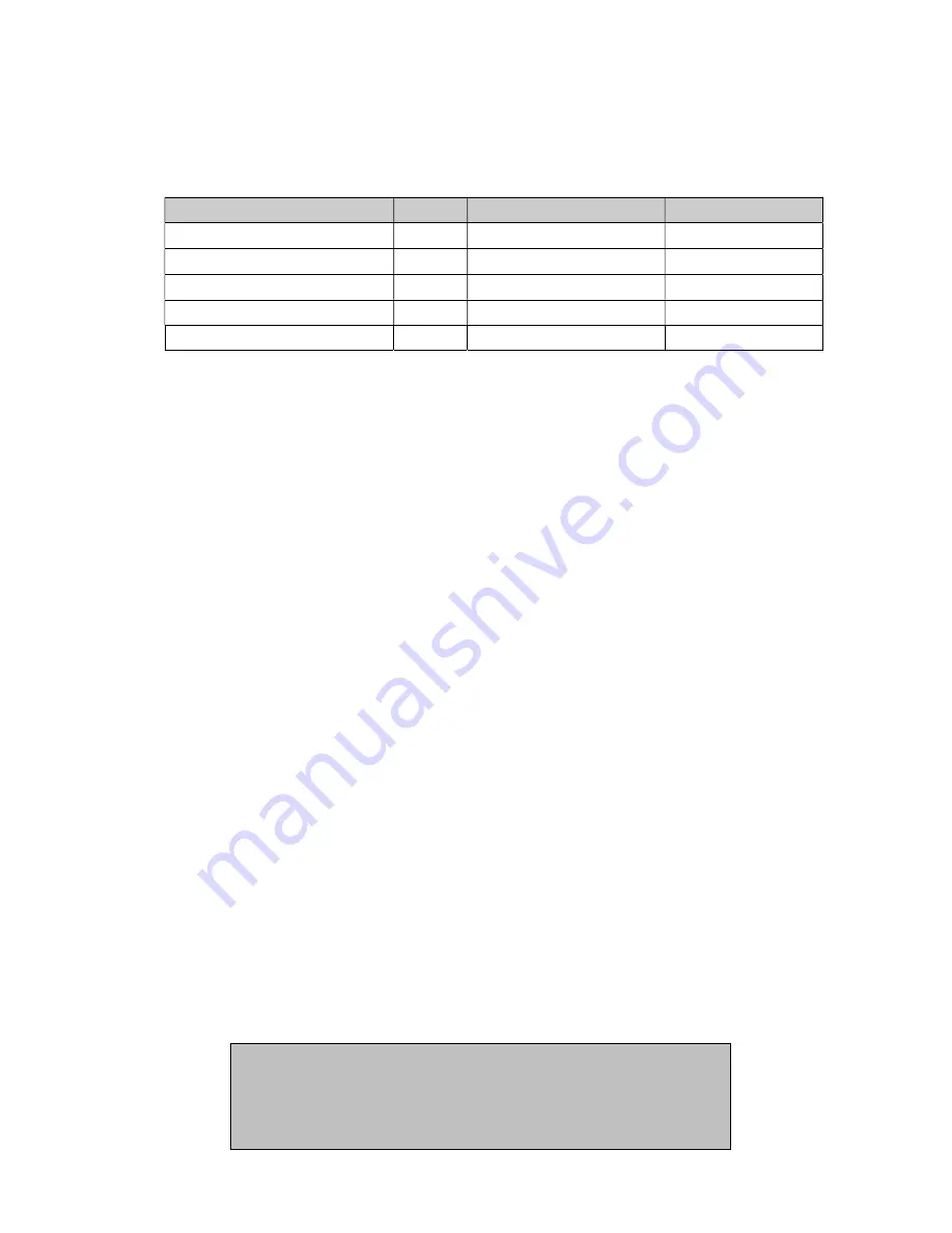
Service/Maintenance
Daily
Weekly
Yearly
Hydraulic oil
Check
1 x replacement
Hydraulic oil filter *)
1 x replacement
Check hoses
(tighten up if needed)
Air filter
1 x replacement
Fuel filter
1 x replacement
*) use only filters with by-pass
Engine service
The engine must be serviced according to the Lombardini service book
Hydraulic Settings
Check the working pressure by means of test equipment.
The test equipment must
comprise a pressure gauge, a flow meter and a valve for adjustment of pressure.
The pressure relief valves are placed on the valve block. There are two pressure
relief valves (one for each hydraulic circuit), and they must be adjusted individually.
The pressure relief valves are marked with B and C respectively.
1. Connect the test equipment to connection B, start the powerpack and move the B
lever to ON and the A and C levers to OFF. Then close the valve on the test
equipment and adjust the pressure relief valve B according to the technical data.
Adjust the pressure relief valve by loosening the lock nut and turning the
adjustment screw in or out. “In” increases the pressure, and “out” decreases the
pressure.
Retighten the lock nut after adjustment.
Connect the test equipment to connection C, start the powerpack and move lever
C to ON and levers A and B to OFF. Then close the valve on the test equipment
and adjust the pressure relief valve C according to the technical data.
2. Having adjusted the pressure relief valves correctly, set the working pressure to
100 bar by means of the valve on the test equipment. At 100 bar the oil flow
should correspond to the flow rate which the lever is set at (see Setting of Flow).
If correct pressure/oil flow cannot be achieved by following
the above instructions, the powerpack must be re-adjusted.
If the pressure/oil flow is then still incorrect, the pump is
defect and must be replaced.

