HY16F3981
IDE
Hardware User’s Manual
© 2017~2022 HYCON Technology Corp
APD-HY16IDE012-V02_EN
page9
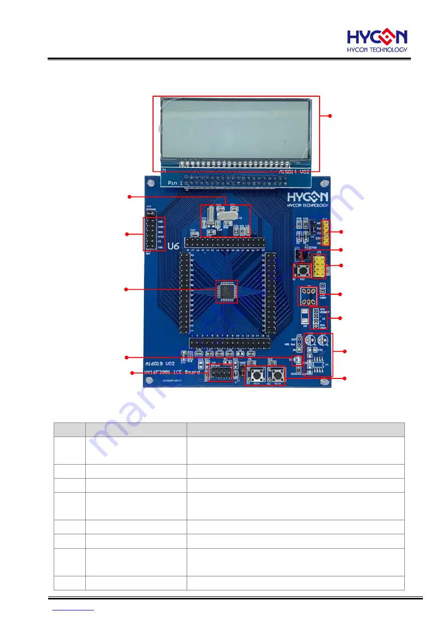
5. Hardware Target Board Introduction
1. 4Com x 17Seg LCD Panel
11. HY16F3981-L064
4. EDM port
8. Tack Switch x 2
7. Power Management
9. External HSXT 4MHz
and LSXT 32768Hz
13. Bridge Sensor
Connector
10. 4 wires SPI
connector
6. JP8,JP9
12. Power LED
5. External power switch
2. Writer connector(5pin)
3. MCU reset switch
5.1. Target Board Features
No.
Name
Description
1
4Com*17Seg
LCD Panel
See Chapter 6 for details
2
Writer connector
Programming IC use
3
MCU reset switch
Reset MCU is used
4
EDM Port
Connection Mini Link
(
See Section 4.3 ICE Connection for details
)
5
External power switch
see section 5.2
6
JP8,JP9
External Power (
see section 5.2
)
7
Power Management
External power supply voltage regulator circuit
(see section 5.2)
8
Tack Switch*2
S2 and S3 are Tack Switches
.


