4
−
7
33
Machine installation
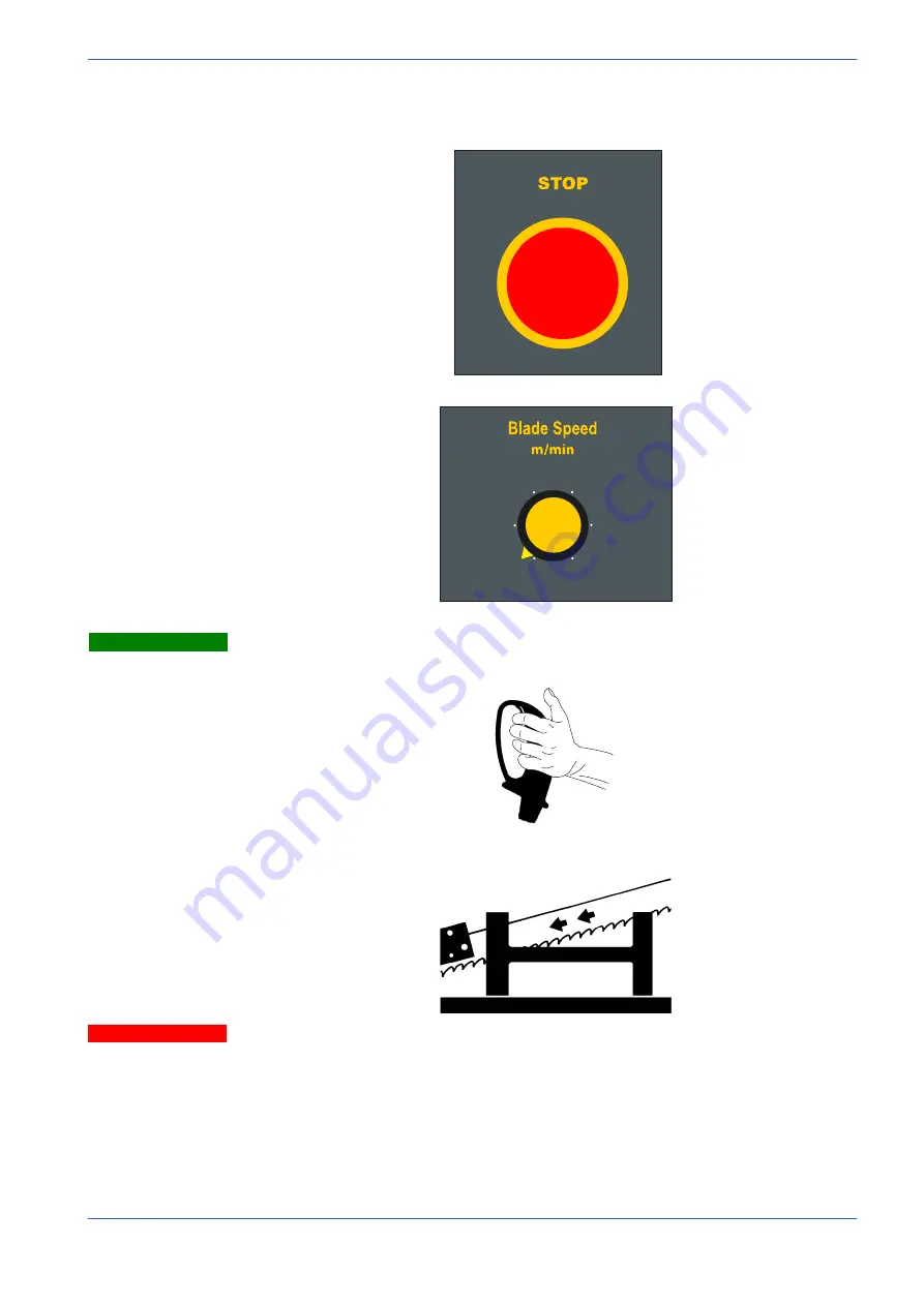
make sure that the machine is not in an emergency condition (red mush
room-head pushbutton released);
select cutting speed using the inverter.
115
15
35
55
75
95
Check that the cutting head descent speed adjuster is at zero.
operate the jog button on the manual head control lever;
if all the above operations have been carried out correctly, the blade motor
will start up and the blade will start rotating.
Ensure that the blade moves in the correct direction as shown in the
above figure.
If it does not, simply reverse two of the phase wires on the ma-
chine power supply input.
The sawing machine is now ready to start the work for which it was designed.
Chapter 5 provides a detailed description of the various functions of the machine
and its operating cycles.
Warning
Attention
Summary of Contents for DM-1215
Page 1: ...USE AND MAINTENANCE MANUAL YEAR OF MANUFACTURE ______________ DM 1215 EN ...
Page 2: ......
Page 4: ......
Page 34: ......
Page 53: ...6 7 52 Diagrams exploded views and replace Standardised Wiring Diagrams ...
Page 54: ...6 8 53 Use and maintenance manual DM 1215 ...
Page 55: ...6 9 54 Diagrams exploded views and replace ...
Page 56: ...6 10 55 Use and maintenance manual DM 1215 F6 F7 F8 F3 F4 F5 RT4 ...
Page 57: ...6 11 56 Diagrams exploded views and replace F1 F2 F9 ...
Page 58: ...6 12 57 Use and maintenance manual DM 1215 S4 KSTO S8 S4 K01 ...
Page 59: ...6 13 58 Diagrams exploded views and replace KSTO KSTO RT4 ...
Page 61: ...6 15 60 Diagrams exploded views and replace ...
Page 62: ...6 16 61 Use and maintenance manual DM 1215 ...
Page 63: ...6 17 62 Diagrams exploded views and replace ...
Page 64: ...6 18 63 Use and maintenance manual DM 1215 ...
Page 65: ...6 19 64 Diagrams exploded views and replace ...
Page 66: ...6 20 65 Use and maintenance manual DM 1215 ...
Page 67: ...6 21 66 Diagrams exploded views and replace ...
Page 68: ...6 22 67 Use and maintenance manual DM 1215 ...
Page 69: ...6 23 68 Diagrams exploded views and replace ...
Page 70: ...6 24 69 Use and maintenance manual DM 1215 ...
Page 71: ...6 25 70 Front flywheel assembly ...
Page 74: ...6 28 73 Use and maintenance manual DM 1215 Motor flywheel assembly ...
Page 77: ...6 31 76 Cutting head cover ...
Page 79: ...6 33 78 Vice assembly ...
Page 81: ...6 35 80 Base assembly ...
Page 83: ...6 37 82 Control panel ...
Page 85: ...6 39 84 Fixed work table and turntable ...
Page 88: ...6 42 87 Use and maintenance manual DM 1215 Cylinder unit ...
Page 90: ...6 44 89 Use and maintenance manual DM 1215 Laser and lamp group ...
Page 92: ......
Page 132: ......
Page 136: ......


