7
−
5
95
Adjustments
Blade guide parts
Band saw blades offer enormous advantages to cutting applications, without
requiring any special skills by the operator. A description follows of the blade
guide adjustments required to ensure correct operation of the saw.
Blade guide heads
The first blade adjustment involves adjustment of the heads. The blade guide
heads comprise the blade guide plates which ensure correct longitudinal align
ment, the blade steady buttons which control vertical blade flexure, and the
coolant supply cocks.
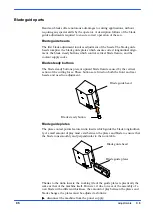
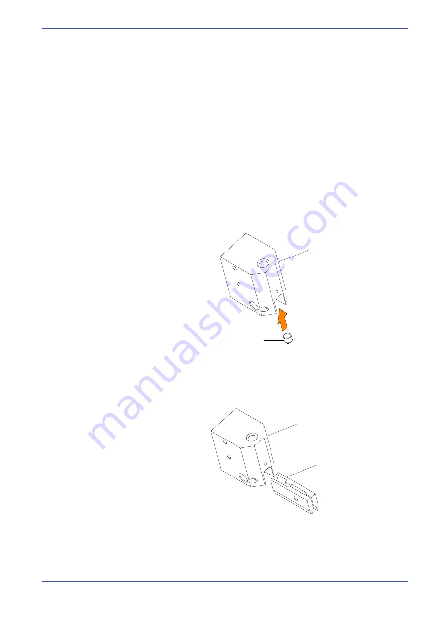
Blade steady buttons
The blade steady buttons prevent upward blade flexure caused by the vertical
action of the cutting force. These buttons are fitted on both the front and rear
heads, and need no adjustment.
Blade steady button
Blade guide head
Blade guide plates
The plate contact points feature widia inserts which guide the blade longitudinal
ly. A small amount of play must exist between the plates and blade to ensure that
the blade runs smoothly and perpendicular to the work table.
Blade guide head
Blade guide plates
Thanks to the widia inserts, the working life of the guide plates is practically the
same as that of the machine itself. However, if due to wear or the assembly of a
new blade with a different thickness, the amount of play between the plates and
blade changes, the plates must be adjusted as follows:
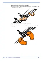
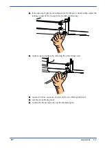
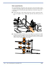
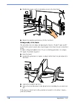
disconnect the machine from the power supply;
Summary of Contents for DM-1215
Page 1: ...USE AND MAINTENANCE MANUAL YEAR OF MANUFACTURE ______________ DM 1215 EN ...
Page 2: ......
Page 4: ......
Page 34: ......
Page 53: ...6 7 52 Diagrams exploded views and replace Standardised Wiring Diagrams ...
Page 54: ...6 8 53 Use and maintenance manual DM 1215 ...
Page 55: ...6 9 54 Diagrams exploded views and replace ...
Page 56: ...6 10 55 Use and maintenance manual DM 1215 F6 F7 F8 F3 F4 F5 RT4 ...
Page 57: ...6 11 56 Diagrams exploded views and replace F1 F2 F9 ...
Page 58: ...6 12 57 Use and maintenance manual DM 1215 S4 KSTO S8 S4 K01 ...
Page 59: ...6 13 58 Diagrams exploded views and replace KSTO KSTO RT4 ...
Page 61: ...6 15 60 Diagrams exploded views and replace ...
Page 62: ...6 16 61 Use and maintenance manual DM 1215 ...
Page 63: ...6 17 62 Diagrams exploded views and replace ...
Page 64: ...6 18 63 Use and maintenance manual DM 1215 ...
Page 65: ...6 19 64 Diagrams exploded views and replace ...
Page 66: ...6 20 65 Use and maintenance manual DM 1215 ...
Page 67: ...6 21 66 Diagrams exploded views and replace ...
Page 68: ...6 22 67 Use and maintenance manual DM 1215 ...
Page 69: ...6 23 68 Diagrams exploded views and replace ...
Page 70: ...6 24 69 Use and maintenance manual DM 1215 ...
Page 71: ...6 25 70 Front flywheel assembly ...
Page 74: ...6 28 73 Use and maintenance manual DM 1215 Motor flywheel assembly ...
Page 77: ...6 31 76 Cutting head cover ...
Page 79: ...6 33 78 Vice assembly ...
Page 81: ...6 35 80 Base assembly ...
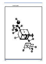
Page 83: ...6 37 82 Control panel ...
Page 85: ...6 39 84 Fixed work table and turntable ...
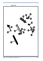
Page 88: ...6 42 87 Use and maintenance manual DM 1215 Cylinder unit ...
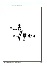
Page 90: ...6 44 89 Use and maintenance manual DM 1215 Laser and lamp group ...
Page 92: ......
Page 132: ......
Page 136: ......

