3.10
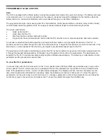
PROGAMMABLE LOGIC CONTROL
Note:
The PLC is equipped with a lithium battery to keep the program stored while the power is shut down. The battery will need
to be replaced every 3 to 5 years, depending on the usage. A visual warning will be displayed on the interface when the
battery drains to a certain level. Batteries can be purchased through your Hyd·Mech distributor.
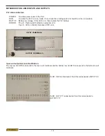
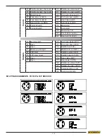
The programmable logic control uses signals from limit switches, control panel switches, encoders (rotary shaft or linear)
and information that is programmed into it to supply accurate automatic length control and sawing functions.
The inputs used include:
•
Head up limit switch
•
Head down limit switch
•
Machine function switches and push buttons
•
A signal from the auto/manual push button (tells the PLC whether auto or manual operation has been selected).
An encoder is attached the shuttle assembly and travels with the shuttle to provide length information to the PLC. A
proximity sensor is mounted through the rear of the idler wheel box. A target for this sensor is mounted on the back of the
idler wheel, or, all six spokes of the wheel may be targets to provide blade speed input to the PLC.
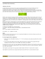
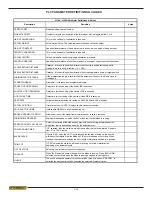
The programmed information includes logic put into the PLC by the manufacturer, as well as information programmed into
it, through the keypad during assembly. Information from the plant is referred to as the parameters. The parameters are
important for the PLC to provide accurate sawing lengths and blade speed display. The following is a description of each
parameter and the procedure to access them.
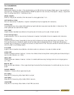
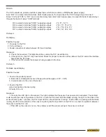
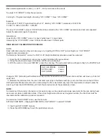
To view the PLC parameters:
In manual mode, with the front vise switch in the “close” position press FWD and REV key simultaneously (not more the
0.5 sec apart). The PLC will prompt you for a password that can be obtained from the Hyd·Mech Group Limited Service
Dept. If the password is correct, a screen of parameters will appear. The display will show four lines of parameters at a
time. If the length control calibration is necessary, follow the calibration procedure in this section. To move through the
parameters use the cursor keys to scroll up or down. To change a parameter, cursor to that parameter line and using the
number keys type in the new value and press enter. To leave the parameters press the Auto/Man key.
Summary of Contents for H18 A
Page 2: ......
Page 12: ...0 8 Item 391938 Chip Augar Item 391335 Item 391340 ...
Page 13: ...0 9 Item 391397 Item 392801 Fixed Vise Shuttle Vise Item 392801 ...
Page 14: ......
Page 16: ...1 2 LIFTING INSTRUCTIONS ...
Page 59: ...4 1 ELECTRICAL SCHEMATICS SEE PDF ON ATTACHED CD SECTION 4 ELECTRICAL ...
Page 60: ...4 2 ...
Page 64: ...6 2 ...
Page 65: ...7 1 SECTION 7 OPTIONS OPTIONAL ASSEMBLY DRAWINGS SEE PDF ON ATTACHED CD ...
Page 66: ...7 2 ...
Page 69: ...8 3 H18SV H22SV LIFTING INSTRUCTIONS ...
Page 70: ...8 4 H18SV LAYOUT ...
Page 71: ...8 5 H22SV LAYOUT ...
Page 72: ...8 6 ...
Page 74: ...9 2 ...

