3.11
PLC PARAMETERS
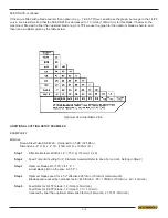
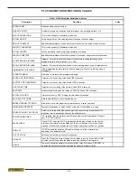
SPEED CONST
Blade speed adjustment number. If the actual blade speed is different than the displayed blade speed, a new speed factor
will need to be calculated (providing the WHEEL TRGETS parameter is set correctly). Actual speed ÷ d adjustment
factor X existing speed factor = New Speed Factor
WHEEL TRGETS
Number of targets per revolution of the idler wheel. Can be toggled either 1 or 6.
HGT CLB (Press Enter)
This is to be used only if calibration is required. Call Hyd·Mech Service department for instruction.
ACTUAL HGT
Actual Height Value. Value entered after performing height calibration procedure (described later in this section). This
value represents the head full stroke height.
HGT CONST
Height constant. Specifies linear distance of head movement in inches per one pulse of head encoder.
LTH CLB (Press Enter)
Length calibration. This is to be used only if calibration is required. Call Hyd·Mech Service department for instruction.
ACTUAL LTH
Actual Length Value. Value entered after performing length calibration procedure (described later in this section). The
PLC uses this value to calculate its length encoder resolution and stroke parameter. Note: If Calibration Procedure is
activated and not completed, or activated and a value not entered for ACT LTH, this value will reset to 00.000 and the PLC
will not be able to count/display lengths.
LTH CONST
Length constant. Specifies linear distance of shuttle movement in inches per one pulse of shuttle encoder.
ACCEL DIST
Shuttle acceleration distance. Distance, in inches, the shuttle will travel slowly before reaching fast speed while starting to
move in either direction. (i.e. 1.000).
DECEL DIST
Shuttle deceleration distance. Distance, in inches, the shuttle will travel slowly reaching before home or target position.
(i.e. 1.000)
MIN FST DIST
Minimum fast speed distance. If the programmed length is smaller than this parameter, the shuttle will only move in slow
speed.
TARGET WINDOW
All/- tolerance from programmed length.
FVO DWELL
Delay time for the opening of the fixed VISE in seconds.
SVO DWELL
Delay time for the opening of the shuttle VISE in seconds.
CLOSE TIME
Delay time for the closing of the shuttle or fixed VISE in seconds.
Summary of Contents for H18 A
Page 2: ......
Page 12: ...0 8 Item 391938 Chip Augar Item 391335 Item 391340 ...
Page 13: ...0 9 Item 391397 Item 392801 Fixed Vise Shuttle Vise Item 392801 ...
Page 14: ......
Page 16: ...1 2 LIFTING INSTRUCTIONS ...
Page 59: ...4 1 ELECTRICAL SCHEMATICS SEE PDF ON ATTACHED CD SECTION 4 ELECTRICAL ...
Page 60: ...4 2 ...
Page 64: ...6 2 ...
Page 65: ...7 1 SECTION 7 OPTIONS OPTIONAL ASSEMBLY DRAWINGS SEE PDF ON ATTACHED CD ...
Page 66: ...7 2 ...
Page 69: ...8 3 H18SV H22SV LIFTING INSTRUCTIONS ...
Page 70: ...8 4 H18SV LAYOUT ...
Page 71: ...8 5 H22SV LAYOUT ...
Page 72: ...8 6 ...
Page 74: ...9 2 ...

