Pg 3.13
S23H
BLADE TRACKING ADJUSTMENT, CONTINUED
10B.
Drive Wheel Adjustment. -- On the wall behind the drive wheel are two adjusting
bolt assemblies and two hex bolts. Loosen all four of them with a 3/4" socket and turn
the larger hex head bolts 1/4 turn with a 1 1/8" socket and extension and then tighten
the two bolts in the assemblies, then tighten the two hex bolts at the left. Turning the 1
1/8" bolts clockwise will pull the blade in and turning counter clockwise will push the
blade out. Each 1/4 turn will move the blade approximtely .02".
11.
Check the blade brush adjustment (as shown below) to be sure the blade is being
cleaned properly.
BLADE GUIDE ADJUSTMENT
At the bottom of the guide arms are the carbide blade guide assemblies, the
photo below shows the carbide locking handle. These assemblies will need to
be adjusted occasionally as the carbide pads become worn. To adjust properly,
follow this simple procedure. Loosen the hex nut on the locking handle with a 9/
16 wrench and turn the handle clockwise until it rests against the coolant tap on
the idler guide arm or the roll pin on the drive guide arm. Turn the set screw
clock wise with a 3/16 allen key until tight and then loosen 1/8 of a turn and
tighten the hex nut. This should put just enough pressure on the blade to permit
you to push the blade down approximately 1/8".
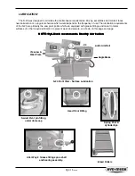
Idler guide arm carbide
locking handle in the
locked position.
Drive wheel
tracking bolt
assemblies
BLADE BRUSH ADJUSTMENT
The S-23 leaves the factory with the blade brush adjusted for maximum life of
the brush. This setting places the ends of the blade brush wires so as to contact
the blade at the bottom of the blade gullets. The plastic drive wheel that is driven
by the drive wheel face should be held against the blade face with the minimum
force that is necessary. As the blade brush wears it is necessary to periodically
readjust it.
As shown, there are two springs on socket head screws holding the brush
assembly against the blade. There is also an adjusting socket set screw with a
hex nut on it. Loosen the hex nut with a 9/16" wrench and turn the set screw
counter clockwise with a 3/16" allen key. This will move the brush closer to the
blade. Adjust the set screw so that the brush cleans to the bottom of the blade
gullets and tighten the hex nut.
Blade brush
adjusting screw.
Summary of Contents for S-23H
Page 1: ...I N B A N D S A W T E C H N O L O G Y OPERATIONS MAINTENANCE M A N UA L ...
Page 3: ...THIS PAGE INTENTIONALLY LEFT BLANK ...
Page 6: ...SECTION 1 INSTALLATION SECTION 1 INSTALLATION ...
Page 7: ...SECTION 1 INSTALLATION ...
Page 12: ...SECTION 2 OPERATING INSTRUCTIONS SECTION 2 OPERATING INSTRUCTIONS ...
Page 13: ...SECTION 2 OPERATING INSTRUCTIONS ...
Page 19: ...THIS PAGE INTENTIONALLY LEFT BLANK ...
Page 20: ...SECTION 3 MAINTENANCE AND TROUBLE SHOOTING SECTION 3 MAINTENANCE AND TROUBLE SHOOTING ...
Page 21: ...SECTION 3 MAINTENANCE AND TROUBLE SHOOTING ...
Page 28: ...Pg 3 17 S23H SERVICE RECORD NOTES DATE SERVICED BY COMMENTS ...
Page 29: ...THIS PAGE INTENTIONALLY LEFT BLANK ...
Page 30: ...SECTION 4 ELECTRICAL SYSTEM SECTION 4 ELECTRICAL SYSTEM ...
Page 31: ...SECTION 4 ELECTRICAL SYSTEM ...
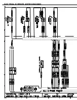
Page 35: ...ELECTRICAL SCHEMATIC WIRING DIAGRAMS ...
Page 36: ......
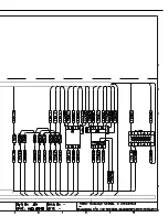
Page 37: ...ELECTRICAL SCHEMATIC WIRING DIAGRAMS ...
Page 38: ......
Page 39: ...THIS PAGE INTENTIONALLY LEFT BLANK ...
Page 40: ...SECTION 5 HYDRAULIC SYSTEM SECTION 5 HYDRAULIC SYSTEM ...
Page 41: ...SECTION 5 HYDRAULIC SYSTEM ...
Page 43: ...Pg 5 28 S22 23H CYLINDER ASSEMBLIES Piston assemblies Gland assemblies ...
Page 44: ...Pg 5 29 S22 23H HYDRAULIC SCHEMATIC and PLUMBING DIAGRAM ...
Page 45: ...Pg 5 30 S22 23H ...
Page 46: ...SECTION 6 MECHANICAL ASSEMBLIES SECTION 6 MECHANICAL ASSEMBLIES ...
Page 47: ...SECTION 6 MECHANICAL ASSEMBLIES ...
Page 48: ...Pg 6 31 S23H 2001a GUIDE ARM CARBIDE ASSEMBLIES SECTION 6 MECHANICAL ASSEMBLIES ...
Page 49: ...Pg 6 32 S23H 2001a BLADE DRIVE ASSEMBLY ...
Page 51: ...Pg 6 34 S23H 2001a HM4A GEAR BOX ASSEMBLY ...
Page 52: ...Pg 6 35 S23H 2001a IDLERWHEEL ASSEMBLY 01 2345 1 345 1 6 7809 849 59 9 3 01 1 ...
Page 53: ...Pg 6 36 S23H 2001a BLADE BRUSH ASSEMBLY ...
Page 54: ...Pg 6 37 S23H 2001a COUNTER BALANCE SPRINGASSEMBLY ...
Page 55: ...Pg 6 38 S23H 2001a PIVOT LINK ASSEMBLY ...
Page 56: ...Pg 6 39 S23H 2001a 0 1 Pivot link parts list ...
Page 57: ...Pg 6 40 S23H 2001a FRONTVISE ASSEMBLY ...
Page 58: ...Pg 6 41 S23H 2001a HYDRAULIC POWER PACK ...
Page 61: ...THIS PAGE INTENTIONALLY LEFT BLANK ...
Page 62: ...SECTION 7 OPTIONAL ASSEMBLIES SECTION 7 OPTIONAL ASSEMBLIES ...
Page 63: ...SECTION 7 OPTIONAL ASSEMBLIES ...
Page 64: ...Pg 7 45 S23H SECTION 7 OPTIONAL ASSEMBLIES WORK STOP ...
Page 67: ...Pg 7 48 S23H 30O MITRE CUTTING ...
Page 68: ...SECTION 8 SPECIFICATIONS SECTION 8 SPECIFICATIONS ...
Page 69: ...SECTION 8 SPECIFICATIONS ...
Page 71: ...Pg 8 50 S23H LAYOUT DRAWINGS ...
Page 72: ...Pg 8 51 S23H ...
Page 73: ...THIS PAGE INTENTIONALLY LEFT BLANK ...
Page 74: ...SECTION 9 WARRANTY SECTION 9 WARRANTY ...
Page 75: ...SECTION 9 WARRANTY ...


