Pg 3.16
S23H
TROUBLE SHOOTING GUIDE
PROBLEM
1.
Cutting out of square vertically.
2.
Cutting out of square horizontally.
3.
Head cylinder creeps:
A)
in hold
B)
in feed position
4.
Blade tracking incorrect.
5.
Blade stalls in cut.
6.
Blade vibrating excessively.
7.
Excessive blade breakage
8.
No coolant flow.
9.
Blade will not start.
10.
Machine stops before cut is
completed or runs on after cut is
completed.
11.
Head will not descend.
12.
No hydraulic functions.
PROBLEM CAUSE
- Carbide guide adjustment incorrect (adjust).
- Feed rate excessive (reduce).
- Blade worn (replace).
- Guide arms too far apart.
- Blade Pitch Incorrect .
- Angle not set correctly(adjust).
- Stock not square in vise. (reset material)
- Angle pointer out of adjustment.
- Stock is not secure in the vise. (reset vise)
- Cylinder seals defective (replace).
- Head valve defective (replace).
- Hydraulic hose leaking.
- Loosen jam nut and adjust pointer with feed rate at zero.
- Improper tension (adjust).
- Tracking needs adjustment.
- Wheel is worn or in poor condition.
- More tension needed.
- Excessive feed rate (reduce).
- Blade pitch incorrect.
- Carbide guides overtightened.
- Blade speed too fast.
- More blade tension needed.
- Guide arms too far apart.
- Feed rate too slow (increase).
- Carbide guides worn or loose (adjust or replace).
NOTE:
New blades tend to vibrate until they are “broken in”.
- Excessive blade tension (reduce).
- Excessive feed rate (reduce).
- Top guide(s) damaged (replace).
- No coolant (add).
- Check coolant ports for blockage.
- Line blockage (blow out lineswith compressed air).
- Coolant pump inoperable (replace).
- Coolant pump has lost its prime, loosen screws, sink pump in
coolant. When coolant starts flowing, tighten screws.
- Lift head off limit switch.
- Control fuse blown.
- Push reset button.
- Adjust head down limit switch bolt.
- Feed Rate Valve is fully closed - pointer is set on "0" or close to "0".
- Pointer is not adjusted. Loosen jam nut, turn knob fully closed,
tighten jam nut with pointer at "0".
- Check for physical interference preventing the ference preventing
the head from falling.
- Check that pressure is minimum 400 psi at gauge. If not, contact
service rep.
Summary of Contents for S-23H
Page 1: ...I N B A N D S A W T E C H N O L O G Y OPERATIONS MAINTENANCE M A N UA L ...
Page 3: ...THIS PAGE INTENTIONALLY LEFT BLANK ...
Page 6: ...SECTION 1 INSTALLATION SECTION 1 INSTALLATION ...
Page 7: ...SECTION 1 INSTALLATION ...
Page 12: ...SECTION 2 OPERATING INSTRUCTIONS SECTION 2 OPERATING INSTRUCTIONS ...
Page 13: ...SECTION 2 OPERATING INSTRUCTIONS ...
Page 19: ...THIS PAGE INTENTIONALLY LEFT BLANK ...
Page 20: ...SECTION 3 MAINTENANCE AND TROUBLE SHOOTING SECTION 3 MAINTENANCE AND TROUBLE SHOOTING ...
Page 21: ...SECTION 3 MAINTENANCE AND TROUBLE SHOOTING ...
Page 28: ...Pg 3 17 S23H SERVICE RECORD NOTES DATE SERVICED BY COMMENTS ...
Page 29: ...THIS PAGE INTENTIONALLY LEFT BLANK ...
Page 30: ...SECTION 4 ELECTRICAL SYSTEM SECTION 4 ELECTRICAL SYSTEM ...
Page 31: ...SECTION 4 ELECTRICAL SYSTEM ...
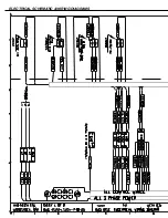
Page 35: ...ELECTRICAL SCHEMATIC WIRING DIAGRAMS ...
Page 36: ......
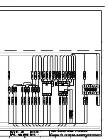
Page 37: ...ELECTRICAL SCHEMATIC WIRING DIAGRAMS ...
Page 38: ......
Page 39: ...THIS PAGE INTENTIONALLY LEFT BLANK ...
Page 40: ...SECTION 5 HYDRAULIC SYSTEM SECTION 5 HYDRAULIC SYSTEM ...
Page 41: ...SECTION 5 HYDRAULIC SYSTEM ...
Page 43: ...Pg 5 28 S22 23H CYLINDER ASSEMBLIES Piston assemblies Gland assemblies ...
Page 44: ...Pg 5 29 S22 23H HYDRAULIC SCHEMATIC and PLUMBING DIAGRAM ...
Page 45: ...Pg 5 30 S22 23H ...
Page 46: ...SECTION 6 MECHANICAL ASSEMBLIES SECTION 6 MECHANICAL ASSEMBLIES ...
Page 47: ...SECTION 6 MECHANICAL ASSEMBLIES ...
Page 48: ...Pg 6 31 S23H 2001a GUIDE ARM CARBIDE ASSEMBLIES SECTION 6 MECHANICAL ASSEMBLIES ...
Page 49: ...Pg 6 32 S23H 2001a BLADE DRIVE ASSEMBLY ...
Page 51: ...Pg 6 34 S23H 2001a HM4A GEAR BOX ASSEMBLY ...
Page 52: ...Pg 6 35 S23H 2001a IDLERWHEEL ASSEMBLY 01 2345 1 345 1 6 7809 849 59 9 3 01 1 ...
Page 53: ...Pg 6 36 S23H 2001a BLADE BRUSH ASSEMBLY ...
Page 54: ...Pg 6 37 S23H 2001a COUNTER BALANCE SPRINGASSEMBLY ...
Page 55: ...Pg 6 38 S23H 2001a PIVOT LINK ASSEMBLY ...
Page 56: ...Pg 6 39 S23H 2001a 0 1 Pivot link parts list ...
Page 57: ...Pg 6 40 S23H 2001a FRONTVISE ASSEMBLY ...
Page 58: ...Pg 6 41 S23H 2001a HYDRAULIC POWER PACK ...
Page 61: ...THIS PAGE INTENTIONALLY LEFT BLANK ...
Page 62: ...SECTION 7 OPTIONAL ASSEMBLIES SECTION 7 OPTIONAL ASSEMBLIES ...
Page 63: ...SECTION 7 OPTIONAL ASSEMBLIES ...
Page 64: ...Pg 7 45 S23H SECTION 7 OPTIONAL ASSEMBLIES WORK STOP ...
Page 67: ...Pg 7 48 S23H 30O MITRE CUTTING ...
Page 68: ...SECTION 8 SPECIFICATIONS SECTION 8 SPECIFICATIONS ...
Page 69: ...SECTION 8 SPECIFICATIONS ...
Page 71: ...Pg 8 50 S23H LAYOUT DRAWINGS ...
Page 72: ...Pg 8 51 S23H ...
Page 73: ...THIS PAGE INTENTIONALLY LEFT BLANK ...
Page 74: ...SECTION 9 WARRANTY SECTION 9 WARRANTY ...
Page 75: ...SECTION 9 WARRANTY ...


