2.2
2.3
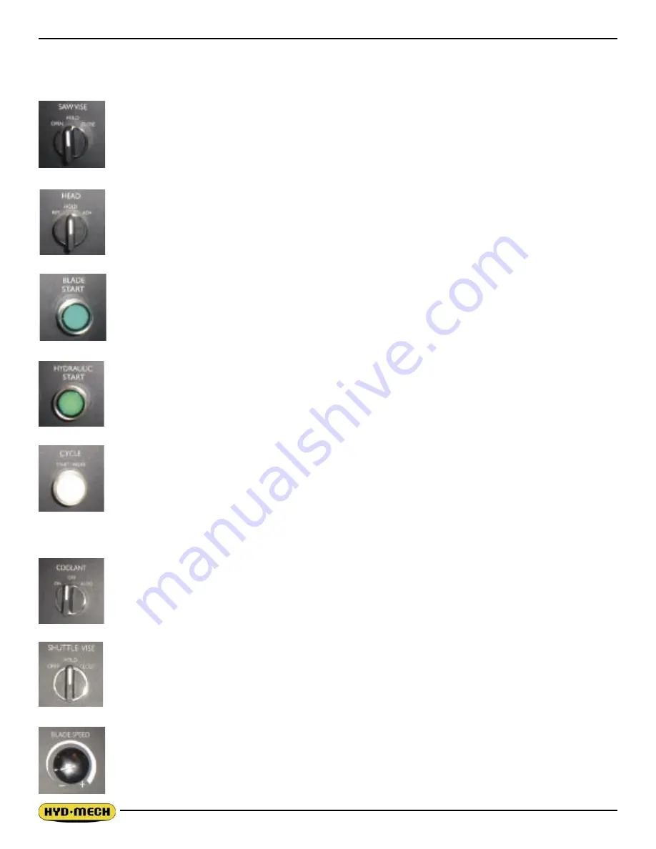
OPERATOR PANEL SWITCHES
TOP ROW
SAW VISE
- (vise between the shuttle & outfeed vises) This switch has three positions, OPEN,
HOLD and CLOSE. With the switch held in the OPEN position the vise will open all the way or
until the switch is released. With the switch in the HOLD position, the vise will stay where it is
and will not move freely although it will not resist a large force indefinitely without creeping. In
CLOSE, the vise will close all the way, or until it encounters enough resistance to stop it.
HEAD CONTROL
- This switch has three positions: RET, HOLD and ADV. The switch is inac-
tive unless the PLC is in manual mode. In the RET. position, the head will go to the back until
the switch is returned to “HOLD”. In the HOLD position the head will stay still. In the ADV. posi-
tion, the head will move forward until it reaches the Head home position. The speed of descent
is controlled by the Head Feed and Head Force Limit controls.
BLADE START
- The blade can be started only when the hydraulics are running in either
manual or auto mode.
NOTE:
In automatic Mode the head will not descend until the blade has been started, which the
PLC will prompt the operator to do so.
HYDRAULIC START
- To start the hydraulic system, the switches for the head and both vises
must be in the “NEUTRAL” position. The “HYDRAULIC START” button must be depressed and
held in momentarily until the PLC display becomes active.
CYCLE START / PAUSE
- This button starts the cutting cycles and will stay illuminated white
until the cycles are completed. The PLC control system will prompt you to start the blade if it is
not running. The machine will then begin the automatic cycle until completed when it will shut
itself off. The current cycle can be PAUSED by pressing this button at any time during a cycle
and restarted by pressing it again.
CENTER ROW
COOLANT
- This switch has three positions, WASH, OFF, and ON. In the WASH position, the
coolant system will operate when there is power to the machine, this allows using the wash gun
to clean the machine. In the OFF position, the coolant system is inactive. In the ON position the
coolant system will only run when the head is descending. This minimizes coolant carry over on
the stock.
SHUTTLE VISE
- This switch has three positions, OPEN, HOLD and CLOSE. With the switch
held in the OPEN position the vise will open all the way or until the switch is released. With the
switch in the HOLD position, the vise will stay where it is and will not move freely although it will
not resist a large force indefinitely without creeping. In CLOSE, the vise will close all the way, or
until it encounters enough resistance to stop it.
BLADE SPEED
- This option is the REMOTE BLADE SPEED. This dial will increase or de-
crease the speed at any time while the blade is running.
Summary of Contents for V-18 APC
Page 2: ......
Page 6: ......
Page 12: ......
Page 28: ......
Page 48: ...4 6 V18 APC 208 240 VOLT ELECTRICAL SCHEMATIC NO OPTIONS ...
Page 49: ...4 7 ...
Page 50: ...4 8 ...
Page 51: ...4 9 ...
Page 52: ...4 10 V18 APC 208 240 VOLT WIRING DIAGRAM NO OPTIONS ...
Page 53: ...4 11 ...
Page 54: ...4 12 ...
Page 55: ...4 13 ...
Page 56: ...4 14 V18 APC 208 240 VOLT INPUT AND OUTPUTS NO OPTIONS ...
Page 57: ...4 15 ...
Page 58: ...4 16 ...
Page 59: ...4 17 ...
Page 60: ...4 18 V18 APC 208 240 VOLT ELECTRICAL SCHEMATIC ...
Page 61: ...4 19 ...
Page 62: ...4 20 ...
Page 63: ...4 21 ...
Page 64: ...4 22 V18 APC 208 240 VOLT WIRING DIAGRAM ...
Page 65: ...4 23 ...
Page 66: ...4 24 ...
Page 67: ...4 25 ...
Page 68: ...4 26 V18 APC 208 240 VOLT INPUT AND OUTPUTS ...
Page 69: ...4 27 ...
Page 70: ...4 28 ...
Page 71: ...4 29 ...
Page 72: ...4 30 V18 APC 480 575 VOLT ELECTRICAL SCHEMATIC NO OPTIONS ...
Page 73: ...4 31 ...
Page 74: ...4 32 ...
Page 75: ...4 33 ...
Page 76: ...4 34 V18 APC 480 575 VOLT ELECTRICAL WIRING DIAGRAM NO OPTIONS ...
Page 77: ...4 35 ...
Page 78: ...4 36 ...
Page 79: ...4 37 ...
Page 80: ...4 38 V18 APC 480 575 VOLT INPUT AND OUTPUT DEVICES NO OPTIONS ...
Page 81: ...4 39 ...
Page 82: ...4 40 ...
Page 83: ...4 41 ...
Page 84: ...4 42 V18 APC 480 575 VOLT ELECTRICAL SCHEMATIC ...
Page 85: ...4 43 ...
Page 86: ...4 44 ...
Page 87: ...4 45 ...
Page 88: ...4 46 V18 APC 480 575 VOLT ELECTRICAL WIRING DIAGRAM ...
Page 89: ...4 47 ...
Page 90: ...4 48 ...
Page 91: ...4 49 ...
Page 92: ...4 50 V18 APC 480 575 VOLT INPUT AND OUTPUT DEVICES ...
Page 93: ...4 51 ...
Page 94: ...4 52 ...
Page 97: ...5 3 V18 APC HYDRAULIC SCHEMATIC ...
Page 98: ...5 4 V18 APC PLUMBING DIAGRAM ...
Page 100: ...6 2 GUIDE ARM ASSEMBLY ...
Page 110: ...6 12 SQUARING VISE ASSEMBLY ...
Page 112: ...6 14 SHUTTLE VISE ASSEMBLY ...
Page 115: ...6 17 COOLANT ASSEMBLY ...
Page 118: ...6 20 CHIP CONVEYOR SHOWN WITH CRANK AND OPTIONAL HYDRAULIC MOTOR ...
Page 124: ...7 4 GUIDE ARM ASSEMBLY FOR EXTENDED HEAD OPTION ...
Page 128: ......
Page 130: ...8 2 ...
Page 131: ...8 3 ...
Page 132: ......


