3.4
3.5
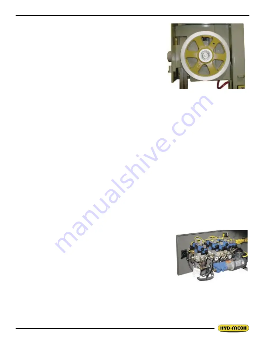
To access the two idler wheel slide
assembly grease nipples the wheel
must be removed. A flexible grease
gun hose with a 45
o
fitting is re-
quired to apply the grease.
HYDRAULIC MAINTENANCE
There are four items of routine maintenance associated with the hy-
draulic system of the V-18 II. With proper maintenance the hydraulic
system of the V-18 should provide years of reliable service.
1. OIL FILTER - Ten micron filtration of the hydraulic oil is pro-
vided by a spin on type filter mounted on the tank return line
as shown below. The element should be changed every 500
working hours or a minimum of at least once per year. Suit-
able replacement elements are:
CANFLO - RSE-30-10
GRESEN - K-23018
LHA - SPE-15-10
ZINGA - AE-10
2. OIL LEVEL - Oil level should be maintained in the upper half
of the level gauge. Normally the rate of oil consumption will be
very low and it should be unnecessary to add oil more often
than at filter changes. Add oil only to the top line on level gauge. The hydraulic tank capacity is 8 US
gallons.
NOTE:
The V-18 II is shipped from the factory with Texaco Rando HD 46 oil. Generally any brand of recognized min-
eral hydraulic oil with the same properties should be compatible with Conoco Super Hydraulic 46 oil, but to
avoid any risk we suggest staying with Texaco Rando HD 46. If it is desirable to change brands, it is necessary
to drain the tank and to fill to1/3 with the new oil. Operate through several full strokes of each cylinder, drain
the tank again, and finally fill the tank with the new brand.
Recommended replacement oils:
Chevron - AW Hydraulic Oil 46
Texaco - Rando HD 46
Mobil - Mobil DTE 25
Esso - NUTO H46
Shell - Tellus 46
3. OIL TEMPERATURE - Oil temperature is indicated by a thermom-
eter contained in the level gauge. Oil temperature during steady
operation should stabilize at about 50 - 55°F above room tempera-
ture. Thus in a 70°F shop one might expect an oil temperature of
about 120°F. Oil temperature should never exceed 160 F°.
OIL PRESSURE - Oil pressure is factory set to 900 psi and should not
require further attention.
Hydraulic tank and manifold as-
sembly are mounted on a door
located on the infeed side of the
base. The level and temperature
gauge is found on the front of the
door.
Summary of Contents for V-18 APC
Page 2: ......
Page 6: ......
Page 12: ......
Page 28: ......
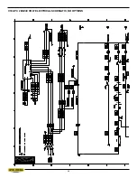
Page 48: ...4 6 V18 APC 208 240 VOLT ELECTRICAL SCHEMATIC NO OPTIONS ...
Page 49: ...4 7 ...
Page 50: ...4 8 ...
Page 51: ...4 9 ...
Page 52: ...4 10 V18 APC 208 240 VOLT WIRING DIAGRAM NO OPTIONS ...
Page 53: ...4 11 ...
Page 54: ...4 12 ...
Page 55: ...4 13 ...
Page 56: ...4 14 V18 APC 208 240 VOLT INPUT AND OUTPUTS NO OPTIONS ...
Page 57: ...4 15 ...
Page 58: ...4 16 ...
Page 59: ...4 17 ...
Page 60: ...4 18 V18 APC 208 240 VOLT ELECTRICAL SCHEMATIC ...
Page 61: ...4 19 ...
Page 62: ...4 20 ...
Page 63: ...4 21 ...
Page 64: ...4 22 V18 APC 208 240 VOLT WIRING DIAGRAM ...
Page 65: ...4 23 ...
Page 66: ...4 24 ...
Page 67: ...4 25 ...
Page 68: ...4 26 V18 APC 208 240 VOLT INPUT AND OUTPUTS ...
Page 69: ...4 27 ...
Page 70: ...4 28 ...
Page 71: ...4 29 ...
Page 72: ...4 30 V18 APC 480 575 VOLT ELECTRICAL SCHEMATIC NO OPTIONS ...
Page 73: ...4 31 ...
Page 74: ...4 32 ...
Page 75: ...4 33 ...
Page 76: ...4 34 V18 APC 480 575 VOLT ELECTRICAL WIRING DIAGRAM NO OPTIONS ...
Page 77: ...4 35 ...
Page 78: ...4 36 ...
Page 79: ...4 37 ...
Page 80: ...4 38 V18 APC 480 575 VOLT INPUT AND OUTPUT DEVICES NO OPTIONS ...
Page 81: ...4 39 ...
Page 82: ...4 40 ...
Page 83: ...4 41 ...
Page 84: ...4 42 V18 APC 480 575 VOLT ELECTRICAL SCHEMATIC ...
Page 85: ...4 43 ...
Page 86: ...4 44 ...
Page 87: ...4 45 ...
Page 88: ...4 46 V18 APC 480 575 VOLT ELECTRICAL WIRING DIAGRAM ...
Page 89: ...4 47 ...
Page 90: ...4 48 ...
Page 91: ...4 49 ...
Page 92: ...4 50 V18 APC 480 575 VOLT INPUT AND OUTPUT DEVICES ...
Page 93: ...4 51 ...
Page 94: ...4 52 ...
Page 97: ...5 3 V18 APC HYDRAULIC SCHEMATIC ...
Page 98: ...5 4 V18 APC PLUMBING DIAGRAM ...
Page 100: ...6 2 GUIDE ARM ASSEMBLY ...
Page 110: ...6 12 SQUARING VISE ASSEMBLY ...
Page 112: ...6 14 SHUTTLE VISE ASSEMBLY ...
Page 115: ...6 17 COOLANT ASSEMBLY ...
Page 118: ...6 20 CHIP CONVEYOR SHOWN WITH CRANK AND OPTIONAL HYDRAULIC MOTOR ...
Page 124: ...7 4 GUIDE ARM ASSEMBLY FOR EXTENDED HEAD OPTION ...
Page 128: ......
Page 130: ...8 2 ...
Page 131: ...8 3 ...
Page 132: ......


