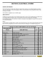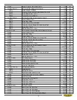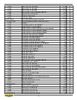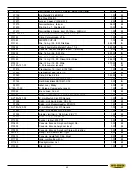
3.10
3.11
cursor on this line press ENTER key and line will read - ANG CLB “ENTER” ON, and cycle light will be flash-
ing. Start the blade and the procedure will execute;
On V18APC: The head will swing slowly to 45 L, and then will come forward for a cut. It will retract, then swing
slowly to 45 R, come forward for a cut, and then retract. At this point the procedure is complete. (Note: If doing
this procedure using material to scribe and calculate new value, a scribe cut at 90° will have to be made before
starting the procedure.)
On M16/20A: The head will swing to 90°, if not already there, move down for a cut, move back up and then
swing to 30°. It will again move down for a cut, and then move back up. At this point the procedure is complete.
The line will then read - ANG CLB “ENTER” OFF. At any point after the procedure has started, or after it has
finished, move the cursor down to the TTL MEAS ANG line, type in the desired value (original or adjusted pa-
rameter), and press ENTER. This value will then be accepted by the PLC. To exit the procedure after comple-
tion, press the EXIT key.
The above procedure is performed to allow for the original parameter to be reinstalled, in a case where there is
no angle display due to loss of this value by PLC memory (electrical & mechanical components ok), or to allow
for the original parameter to be modified, in a case where the angle display is inaccurate, and proper calibra-
tion cannot be performed. (Proper material not available for test cuts.)
For angle troubleshooting details please contact Hyd·Mech Group Limited.
PARAMETER DEFINITIONS
MTL INFEED - (V18A ONLY) MATERIAL INFEED:
Tells PLC which side of the machine material in-feed is on.
ACT LTH - ACTUAL LENGTH:
Value determined by, and entered after, performing the Length Calibration
Procedure. PLC uses this value to calculate its length encoder resolution and
Stroke parameter.
STROKE -
Value determined by the PLC based on the above Actual Length value. This value is automatically
entered by the PLC and cannot be changed through the keypad.
LNG TRG WD - LENGTH TARGET WINDOW:
All / - tolerance from programmed length.
ACC DIST - ACCELERATION DISTANCE:
Distance, in inches, the shuttle will travel slowly before going to
fast speed, when starting to move in either direction. (ie. .250)
DEC DIST - DECELERATION DISTANCE:
Distance, in inches, from the home or target length position, the
shuttle will travel in slow speed. (ie. 1.000)
SLW DIST - SLOW DISTANCE:
Minimum fast speed distance. If programmed length is smaller than this pa-
rameter the PLC will only move the shuttle in slow speed.
FVO DWELL - FRONT VISE OPEN DWELL:
Opening time for the front vise. A value of 100 is approximately 1
second. (ie. 75 = .750 sec.)
SVO DWELL - SHUTTLE VISE OPEN DWELL:
Opening time for the shuttle vise.
CLS TIME - CLOSE TIME:
Closing time for front vise or shuttle vise. (ie. 100 = 1 sec.)
ACT HD MVT - ACTUAL HEAD MOVEMENT:
Value that is determined by, and entered after, performing the
Summary of Contents for V-18 APC
Page 2: ......
Page 6: ......
Page 12: ......
Page 28: ......
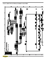
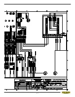
Page 48: ...4 6 V18 APC 208 240 VOLT ELECTRICAL SCHEMATIC NO OPTIONS ...
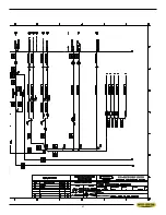
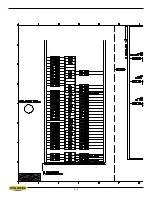
Page 49: ...4 7 ...
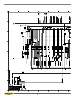
Page 50: ...4 8 ...
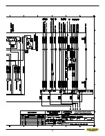
Page 51: ...4 9 ...
Page 52: ...4 10 V18 APC 208 240 VOLT WIRING DIAGRAM NO OPTIONS ...
Page 53: ...4 11 ...
Page 54: ...4 12 ...
Page 55: ...4 13 ...
Page 56: ...4 14 V18 APC 208 240 VOLT INPUT AND OUTPUTS NO OPTIONS ...
Page 57: ...4 15 ...
Page 58: ...4 16 ...
Page 59: ...4 17 ...
Page 60: ...4 18 V18 APC 208 240 VOLT ELECTRICAL SCHEMATIC ...
Page 61: ...4 19 ...
Page 62: ...4 20 ...
Page 63: ...4 21 ...
Page 64: ...4 22 V18 APC 208 240 VOLT WIRING DIAGRAM ...
Page 65: ...4 23 ...
Page 66: ...4 24 ...
Page 67: ...4 25 ...
Page 68: ...4 26 V18 APC 208 240 VOLT INPUT AND OUTPUTS ...
Page 69: ...4 27 ...
Page 70: ...4 28 ...
Page 71: ...4 29 ...
Page 72: ...4 30 V18 APC 480 575 VOLT ELECTRICAL SCHEMATIC NO OPTIONS ...
Page 73: ...4 31 ...
Page 74: ...4 32 ...
Page 75: ...4 33 ...
Page 76: ...4 34 V18 APC 480 575 VOLT ELECTRICAL WIRING DIAGRAM NO OPTIONS ...
Page 77: ...4 35 ...
Page 78: ...4 36 ...
Page 79: ...4 37 ...
Page 80: ...4 38 V18 APC 480 575 VOLT INPUT AND OUTPUT DEVICES NO OPTIONS ...
Page 81: ...4 39 ...
Page 82: ...4 40 ...
Page 83: ...4 41 ...
Page 84: ...4 42 V18 APC 480 575 VOLT ELECTRICAL SCHEMATIC ...
Page 85: ...4 43 ...
Page 86: ...4 44 ...
Page 87: ...4 45 ...
Page 88: ...4 46 V18 APC 480 575 VOLT ELECTRICAL WIRING DIAGRAM ...
Page 89: ...4 47 ...
Page 90: ...4 48 ...
Page 91: ...4 49 ...
Page 92: ...4 50 V18 APC 480 575 VOLT INPUT AND OUTPUT DEVICES ...
Page 93: ...4 51 ...
Page 94: ...4 52 ...
Page 97: ...5 3 V18 APC HYDRAULIC SCHEMATIC ...
Page 98: ...5 4 V18 APC PLUMBING DIAGRAM ...
Page 100: ...6 2 GUIDE ARM ASSEMBLY ...
Page 110: ...6 12 SQUARING VISE ASSEMBLY ...
Page 112: ...6 14 SHUTTLE VISE ASSEMBLY ...
Page 115: ...6 17 COOLANT ASSEMBLY ...
Page 118: ...6 20 CHIP CONVEYOR SHOWN WITH CRANK AND OPTIONAL HYDRAULIC MOTOR ...
Page 124: ...7 4 GUIDE ARM ASSEMBLY FOR EXTENDED HEAD OPTION ...
Page 128: ......
Page 130: ...8 2 ...
Page 131: ...8 3 ...
Page 132: ......


