3.12
3.13
Head Calibration Procedure. It represents the full travel dis-
tance of the head.
TTL L MEAS ANG - TOTAL LEFT MEASURED ANGLE
: Value determined by, and entered after, performing
the Left Angle Calibration Procedure. PLC uses this
value to calculate its angle encoder resolution.
TTL R MEAS ANG - TOTAL RIGHT MEASURED ANGLE:
As above but for right side angles.
TTL MEAS ANG - TOTAL MEAS ANG:
Only for M16/20 and older V18APC; single value for angle encoder
resolution as above, determined by, and entered after, performing the
Angle Calibration Procedure.
ANG TRG WD - ANGLE TARGET WINDOW:
All / - tolerance from programmed angle.
ANG DEC - ANGLE DECELERATION:
Distance in degrees the head will move in slow speed on approaching
target angle.
BP RADIUS: On M16/20:
The distance in inches from the front side of the blade to the pivot point of the head.
On V18APC: The distance in inches from the out-feed side of the blade to the pivot point of the head.
This parameter is used, along with DP RADIUS to calculate the correct shuttle length when the head
swings away from 90° (ie. 0.020).
DP RADIUS: On M16/20:
The distance in inches from the inside face of the fixed jaw on the front vise (usually
referred to as the datum line) to the pivot point of the head.
On V18APC: The distance in inches from the top of the cutting table (the datum line on V18) to the
pivot point of the head.
Along with BP RADIUS, used to calculate the correct shuttle length when the head swings away from
90° (ie. 0.082).
SPD FACTOR - SPEED FACTOR:
Blade speed adjustment number. If actual blade speed is different than
displayed blade speed, a new speed factor must be calculated. (Providing
wheel target parameter is set correctly).
Actual speed/Display speed = Adjustment factor
Adjustment factor X Existing speed factor = New speed factor.
WHEEL TRG – WHEEL TARGETS:
Number of targets per revolution of the idler wheel.
M16/20A – 1
V18A-6 (Starting in Jan 99, this changed to 1)
ACT POS
– If this parameter is set to ‘ON’, length display will show actual position.
HLD SHT HM:
If this parameter is set to ‘ON’, the shuttle vise will stay closed at the home position during each
cut.
BRKN PROX:
If this parameter is set to ‘OFF’, if the blade breaks the machine will shut down. If set to ‘ON’,
overrides the broken blade function; machine will be able to continue to run if there is a problem
with the blade speed signal (broken blade speed sender).
BLDE CHAM:
If this parameter is set to ‘ON’, when the AUTO cycle reaches the function of head up (head
retract on V18APC), the shuttle will retract the material away from the blade by 1/8” before the
Summary of Contents for V-18 APC
Page 2: ......
Page 6: ......
Page 12: ......
Page 28: ......
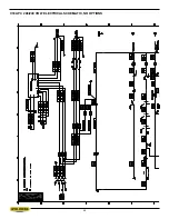
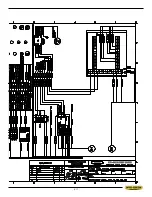
Page 48: ...4 6 V18 APC 208 240 VOLT ELECTRICAL SCHEMATIC NO OPTIONS ...
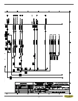
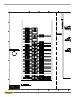
Page 49: ...4 7 ...
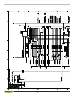
Page 50: ...4 8 ...
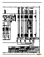
Page 51: ...4 9 ...
Page 52: ...4 10 V18 APC 208 240 VOLT WIRING DIAGRAM NO OPTIONS ...
Page 53: ...4 11 ...
Page 54: ...4 12 ...
Page 55: ...4 13 ...
Page 56: ...4 14 V18 APC 208 240 VOLT INPUT AND OUTPUTS NO OPTIONS ...
Page 57: ...4 15 ...
Page 58: ...4 16 ...
Page 59: ...4 17 ...
Page 60: ...4 18 V18 APC 208 240 VOLT ELECTRICAL SCHEMATIC ...
Page 61: ...4 19 ...
Page 62: ...4 20 ...
Page 63: ...4 21 ...
Page 64: ...4 22 V18 APC 208 240 VOLT WIRING DIAGRAM ...
Page 65: ...4 23 ...
Page 66: ...4 24 ...
Page 67: ...4 25 ...
Page 68: ...4 26 V18 APC 208 240 VOLT INPUT AND OUTPUTS ...
Page 69: ...4 27 ...
Page 70: ...4 28 ...
Page 71: ...4 29 ...
Page 72: ...4 30 V18 APC 480 575 VOLT ELECTRICAL SCHEMATIC NO OPTIONS ...
Page 73: ...4 31 ...
Page 74: ...4 32 ...
Page 75: ...4 33 ...
Page 76: ...4 34 V18 APC 480 575 VOLT ELECTRICAL WIRING DIAGRAM NO OPTIONS ...
Page 77: ...4 35 ...
Page 78: ...4 36 ...
Page 79: ...4 37 ...
Page 80: ...4 38 V18 APC 480 575 VOLT INPUT AND OUTPUT DEVICES NO OPTIONS ...
Page 81: ...4 39 ...
Page 82: ...4 40 ...
Page 83: ...4 41 ...
Page 84: ...4 42 V18 APC 480 575 VOLT ELECTRICAL SCHEMATIC ...
Page 85: ...4 43 ...
Page 86: ...4 44 ...
Page 87: ...4 45 ...
Page 88: ...4 46 V18 APC 480 575 VOLT ELECTRICAL WIRING DIAGRAM ...
Page 89: ...4 47 ...
Page 90: ...4 48 ...
Page 91: ...4 49 ...
Page 92: ...4 50 V18 APC 480 575 VOLT INPUT AND OUTPUT DEVICES ...
Page 93: ...4 51 ...
Page 94: ...4 52 ...
Page 97: ...5 3 V18 APC HYDRAULIC SCHEMATIC ...
Page 98: ...5 4 V18 APC PLUMBING DIAGRAM ...
Page 100: ...6 2 GUIDE ARM ASSEMBLY ...
Page 110: ...6 12 SQUARING VISE ASSEMBLY ...
Page 112: ...6 14 SHUTTLE VISE ASSEMBLY ...
Page 115: ...6 17 COOLANT ASSEMBLY ...
Page 118: ...6 20 CHIP CONVEYOR SHOWN WITH CRANK AND OPTIONAL HYDRAULIC MOTOR ...
Page 124: ...7 4 GUIDE ARM ASSEMBLY FOR EXTENDED HEAD OPTION ...
Page 128: ......
Page 130: ...8 2 ...
Page 131: ...8 3 ...
Page 132: ......


